113
Router ID: 3.3.3.3 Address: 192.168.1.3 GR State: Normal
State: Full Mode: Nbr is Slave Priority: 2
DR: 192.168.1.1 BDR: 192.168.1.3 MTU: 0
Dead timer due in 39 sec
Neighbor is up for 00:01:41
Authentication Sequence: [ 0 ]
Switch A becomes the DR, and Switch C is the BDR.
The full neighbor state means an adjacency has been established. The 2-way neighbor state
means the two routers are not the DR or BDR, and they do not exchange LSAs.
# Display OSPF interface information.
[SwitchA] display ospf interface
OSPF Process 1 with Router ID 1.1.1.1
Interfaces
Area: 0.0.0.0
IP Address Type State Cost Pri DR BDR
192.168.1.1 Broadcast DR 1 100 192.168.1.1 192.168.1.3
[SwitchB] display ospf interface
OSPF Process 1 with Router ID 2.2.2.2
Interfaces
Area: 0.0.0.0
IP Address Type State Cost Pri DR BDR
The interface state DROther means the interface is not the DR/BDR.
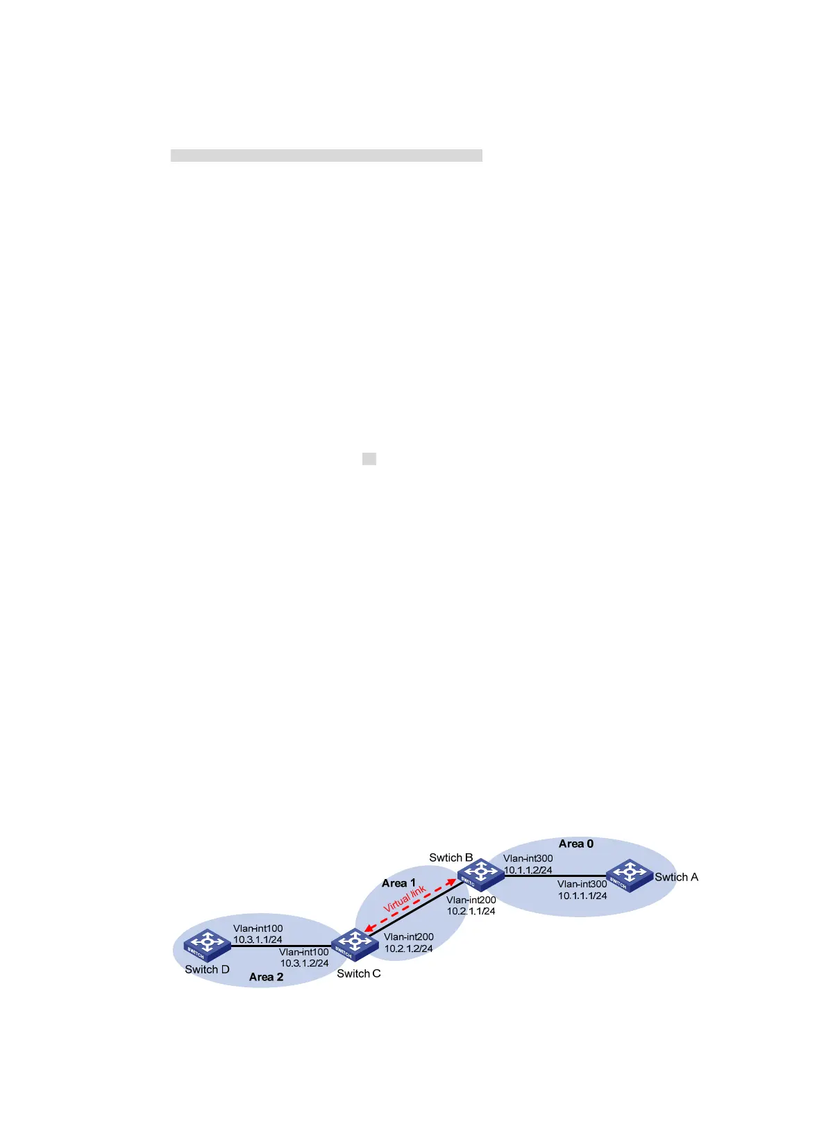
Configuring OSPF virtual links
Network requirements
In Figure 44, Area 2 has no direct connection to Area 0, and Area 1 acts as the Transit Area to connect
Area 2 to Area 0 via a configured virtual link between Switch B and Switch C.
After configuration, Switch B can learn routes to Area 2.
Figure 44 Network diagram
 Loading...


