302
After all switches function properly, perform a master/slave switchover on Switch A to trigger an
OSPFv3 GR operation.
Configuring BFD for OSPFv3
Network requirements
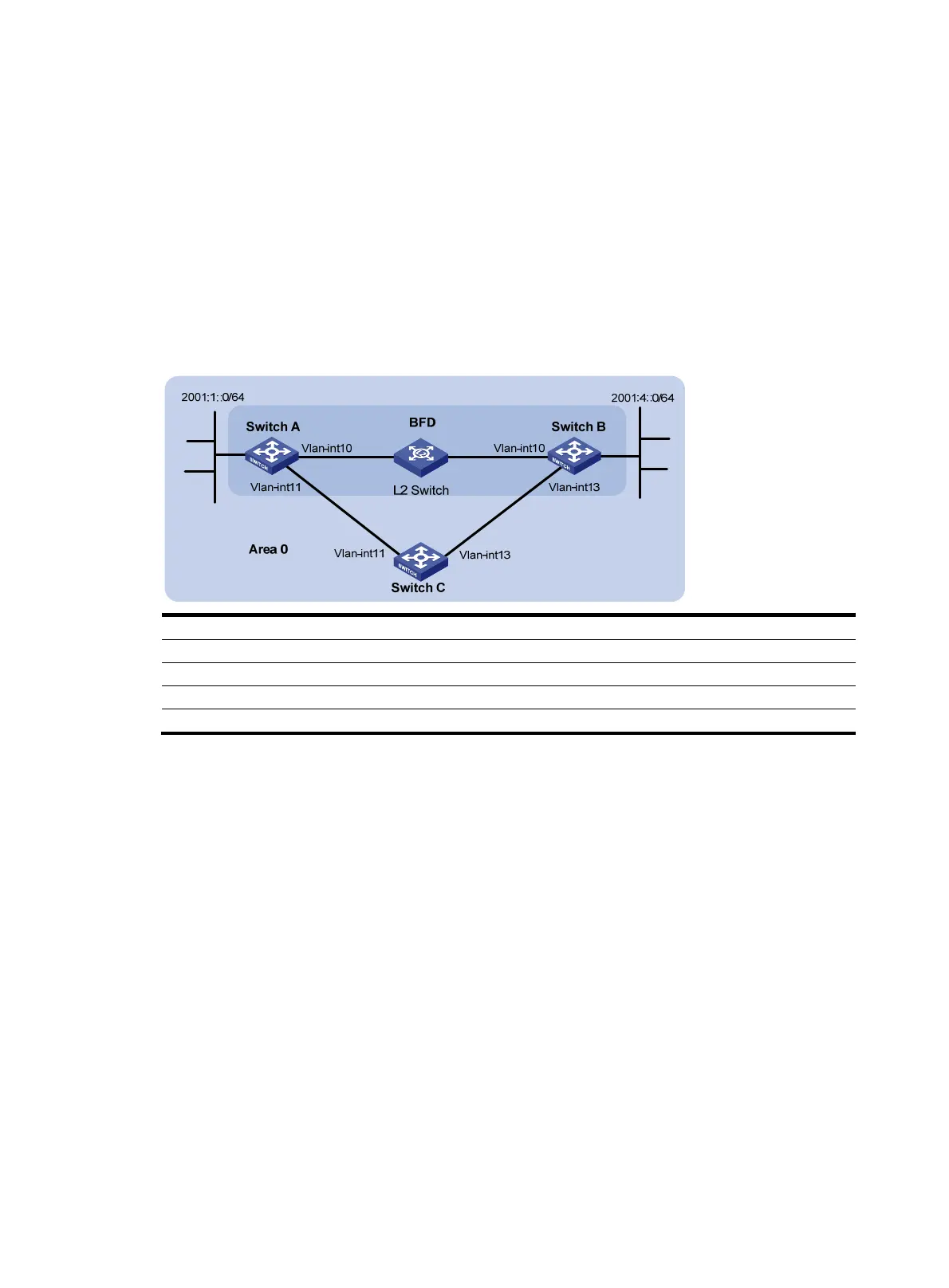
In Figure 110, configure OSPFv3 on Switch A, Switch B and Switch C and configure BFD over the link
Switch A<—>L2 Switch<—>Switch B.
After the link Switch A<—>L2 Switch<—>Switch B fails, BFD can quickly detect the failure and notify
OSPFv3 of the failure. Then Switch A and Switch B communicate through Switch C.
Figure 110 Network diagram
Device Interface IPv6 address
Device
Interface
IPv6 address
Switch A Vlan-int10 2001::1/64
Switch B
Vlan-int10 2001::2/64
Vlan-int11 2001:2::1/64 Vlan-int13 2001:3::2/64
Switch C Vlan-int11 2001:2::2/64
Vlan-int13 2001:3::1/64
Configuration procedure
1. Configure IP addresses for the interfaces. (Details not shown.)
2. Configure OSPF basic functions:
# Configure Switch A. Enable OSPFv3 and configure the router ID as 1.1.1.1.
<SwitchA> system-view
[SwitchA] ipv6
[SwitchA] ospfv3
[SwitchA-ospfv3-1] router-id 1.1.1.1
[SwitchA-ospfv3-1] quit
[SwitchA] interface vlan-interface 10
[SwitchA-Vlan-interface10] ospfv3 1 area 0
[SwitchA-Vlan-interface10] quit
[SwitchA] interface vlan-interface 11
[SwitchA-Vlan-interface11] ospfv3 1 area 0
[SwitchA-Vlan-interface11] quit
# Configure Switch B. Enable OSPFv3 and configure the router ID as 2.2.2.2.
<SwitchB> system-view
[SwitchB] ipv6
 Loading...


