248
# Configure the IBGP connection.
<SwitchC> system-view
[SwitchC] bgp 65009
[SwitchC-bgp] router-id 3.3.3.3
[SwitchC-bgp] peer 9.1.1.1 as-number 65009
# Enable GR capability for BGP.
[SwitchC-bgp] graceful-restart
4. Verify the configuration:
Ping Switch C on Switch A. Meanwhile, perform a master/slave switchover on Switch B. The ping
operation is successful during the whole switchover process.
BFD for BGP configuration example
Network requirements
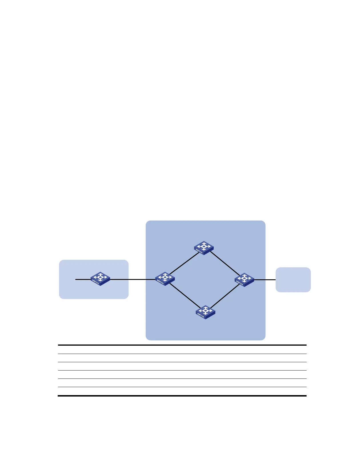
As shown in Figure 97,
• Configure OSPF as the IGP in AS 200.
• Establish two IBGP connections between Switch A and Switch C. When both links are working,
Switch C adopts the link Switch A<—>Switch B<—>Switch C to exchange packets with network
1.1.1.0/24. Configure BFD over the link. Then if the link fails, BFD can quickly detect the failure and
notify it to BGP. Then the link Switch A<—>Switch D<—>Switch C takes effect immediately.
Figure 97 Network diagram
Device Interface IP address
Device
Interface IP address
Switch A Vlan-int100 3.0.1.1/24 Switch C Vlan-int101 3.0.2.2/24
Vlan-int200 2.0.1.1/24
Vlan-int201 2.0.2.2/24
Vlan-int30 30.1.1.1/24
Switch D
Vlan-int200 2.0.1.2/24
Switch B Vlan-int100 3.0.1.2/24 Vlan-int201 2.0.2.1/24
Vlan-int101 3.0.2.1/24
Switch E
Vlan-int30 30.1.1.2/24
Configuration procedure
1. Configure IP addresses for interfaces. (Details not shown.)
Switch A Switch C
AS 200
Switch D
Vlan-int200
Vlan-int201
Switch B
AS 300
Vlan-int101Vlan-int100
Vlan-int100
Vlan-int101
Vlan-int200
Vlan-int201
AS 100
1.1.1.0/24
Vlan-int30 Vlan-int30
Switch E
 Loading...


