41
Configuring an additional metric for a RIP interface
Network requirements
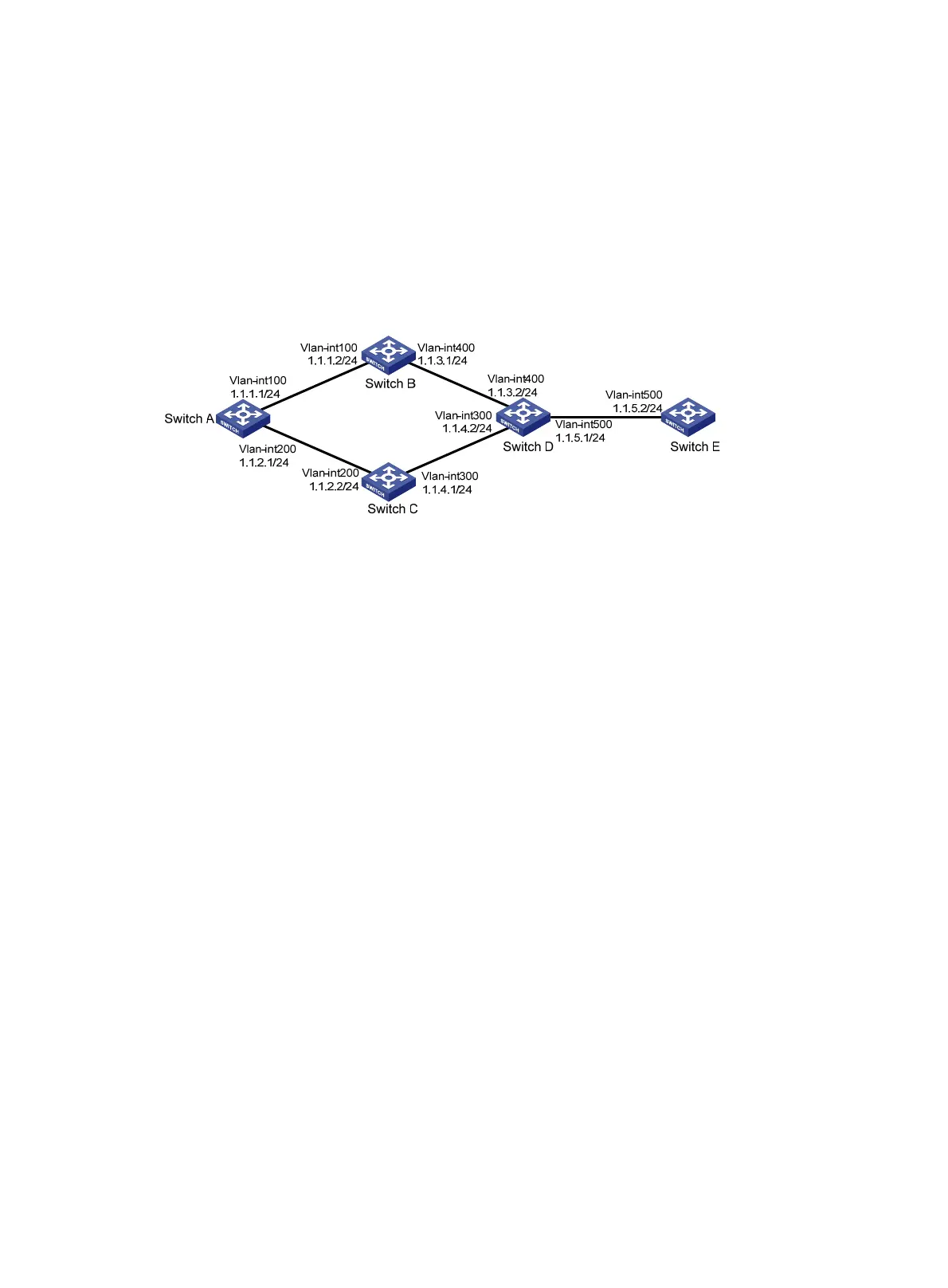
In the following figure, RIP is enabled on all the interfaces of Switch A, Switch B, Switch C, Switch D, and
Switch E. The switches are interconnected through RIPv2.
Switch A has two links to Switch D. The link from Switch B to Switch D is more stable than that from Switch
C to Switch D. Configure an additional metric for RIP routes received through VLAN-interface 200 on
Switch A so that Switch A prefers the 1.1.5.0/24 network learned from Switch B.
Figure 12 Network diagram
Configuration procedure
1. Configure IP addresses for the interfaces. (Details not shown.)
2. Configure RIP basic functions:
# Configure Switch A.
<SwitchA> system-view
[SwitchA] rip 1
[SwitchA-rip-1] network 1.0.0.0
[SwitchA-rip-1] version 2
[SwitchA-rip-1] undo summary
[SwitchA-rip-1] quit
# Configure Switch B.
<SwitchB> system-view
[SwitchB] rip 1
[SwitchB-rip-1] network 1.0.0.0
[SwitchB-rip-1] version 2
[SwitchB-rip-1] undo summary
# Configure Switch C.
<SwitchC> system-view
[SwitchB] rip 1
[SwitchC-rip-1] network 1.0.0.0
[SwitchC-rip-1] version 2
[SwitchC-rip-1] undo summary
# Configure Switch D.
<SwitchD> system-view
[SwitchD] rip 1
[SwitchD-rip-1] network 1.0.0.0
[SwitchD-rip-1] version 2
 Loading...


