181
[SwitchC-isis-1] area-authentication-mode md5 10Sec
[SwitchC-isis-1] quit
5. Configure routing domain authentication. Specify the MD5 authentication mode and password
1020Sec on Switch C and Switch D.
[SwitchC] isis 1
[SwitchC-isis-1] domain-authentication-mode md5 1020Sec
[SwitchC-isis-1] quit
[SwitchD] isis 1
[SwitchD-isis-1] domain-authentication-mode md5 1020Sec
Configuring BFD for IS-IS
Network requirements
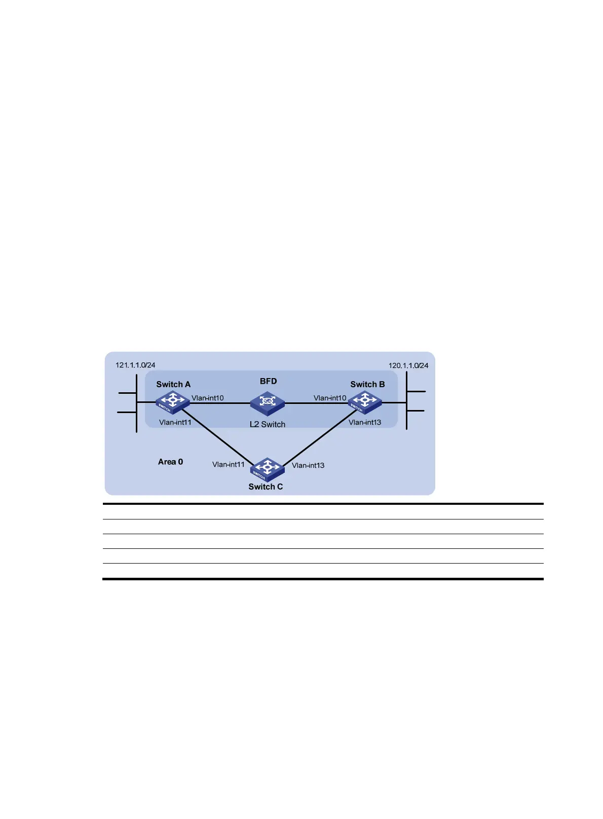
• As shown in Figure 70, IS-IS is enabled on Switch A, Switch B and Switch C that are reachable to
each other at the network layer.
• After the link over which Switch A and Switch B communicate through the Layer-2 switch fails, BFD
can quickly detect the failure and notify IS-IS of the failure. Switch A and Switch B then communicate
through Switch C.
Figure 70 Network diagram for BFD configuration on an IS-IS link
Device Interface IP address
Device
Interface
IP address
Switch A Vlan-int10 10.1.0.102/24 Switch B Vlan-int10 10.1.0.100/24
Vlan-int11 11.1.1.1/24
Vlan-int13 13.1.1.1/24
Switch C Vlan-int11 11.1.1.2/24
Vlan-int13 13.1.1.2/24
Configuration procedure
1. Configure IP addresses for interfaces (Details not shown.).
2. Configure IS-IS basic functions.
# Configure Switch A.
<SwitchA> system-view
[SwitchA] isis
[SwitchA-isis-1] network-entity 10.0000.0000.0001.00
[SwitchA-isis-1] quit
[SwitchA] interface vlan-interface 10
[SwitchA-Vlan-interface10] isis enable
 Loading...


