236
# Display the BGP routing table on Switch A.
[SwitchA] display bgp routing-table
Total Number of Routes: 3
BGP Local router ID is 1.1.1.1
Status codes: * - valid, ^ - VPNv4 best, > - best, d - damped,
h - history, i - internal, s - suppressed, S - Stale
Origin : i - IGP, e - EGP, ? - incomplete
Network NextHop MED LocPrf PrefVal Path/Ogn
*> 8.1.1.0/24 0.0.0.0 0 0 i
*> 9.1.1.0/24 3.1.1.1 0 0 65009i
*> 3.1.2.1 0 0 65009i
{ T h e r o u t e 9.1.1. 0 / 24 h a s t wo n e x t h o p s 3.1.1.1 a n d 3.1. 2.1, b o t h o f w h i c h a re m a r k e d w i t h a
greater-than sign (>), indicating they are the best routes.
{ By using the display ip routing-table command, you can find two routes to 9.1.1.0/24: one with
next hop 3.1.1.1 and outbound interface VLAN-interface 200, the other with next hop 3.1.2.1
and outbound interface VLAN-interface 300.
BGP community configuration example
Network requirements
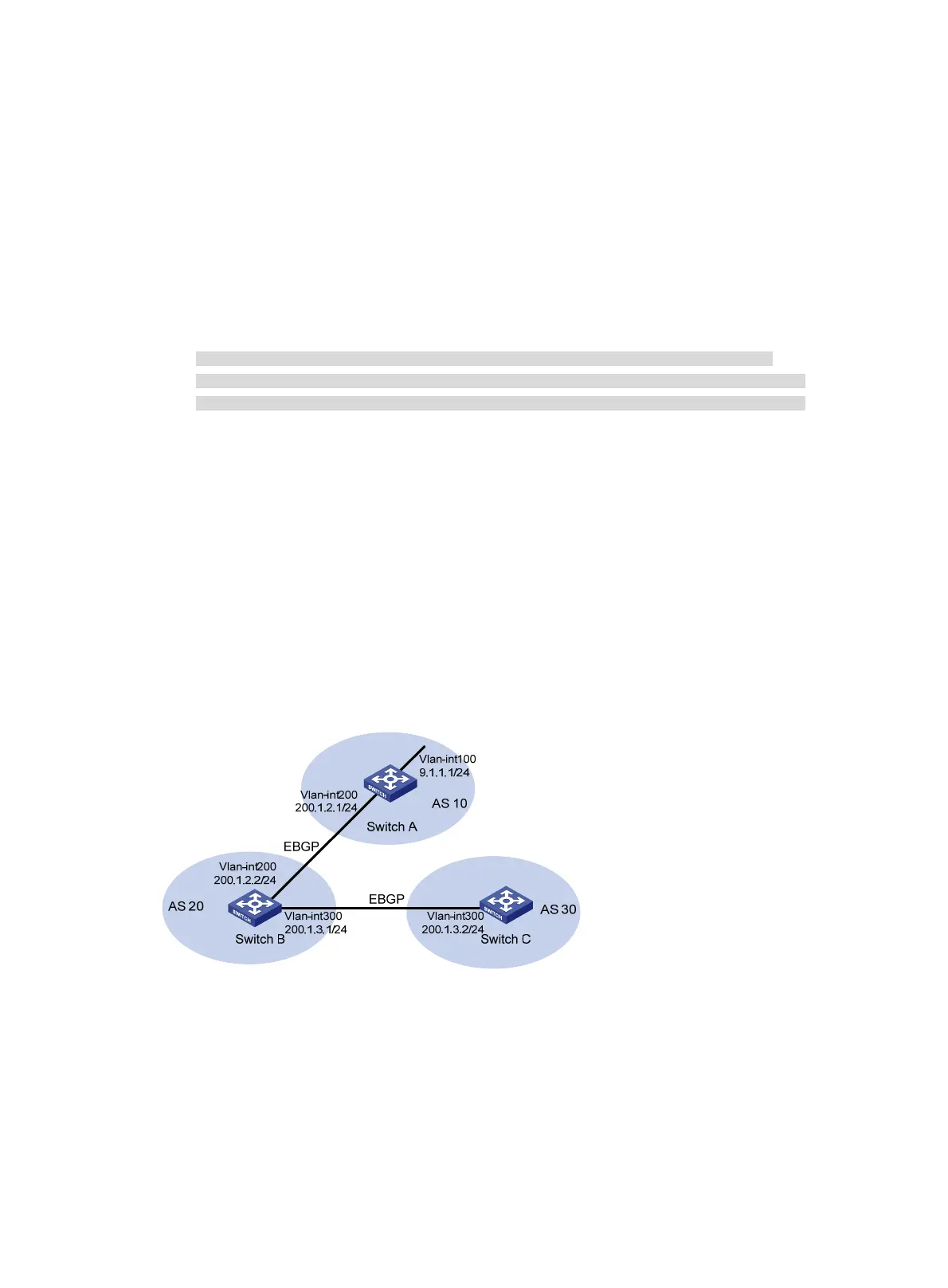
As shown in Figure 92, Switch B establishes EBGP connections with Switch A and C. Configure
NO_EXPORT community attribute on Switch A to make routes from AS 10 not advertised by AS 20 to any
other AS.
Figure 92 Network diagram
Configuration procedure
1. Configure IP addresses for interfaces. (Details not shown.)
2. Configure EBGP:
# Configure Switch A.
<SwitchA> system-view
[SwitchA] bgp 10
[SwitchA-bgp] router-id 1.1.1.1
 Loading...


