18
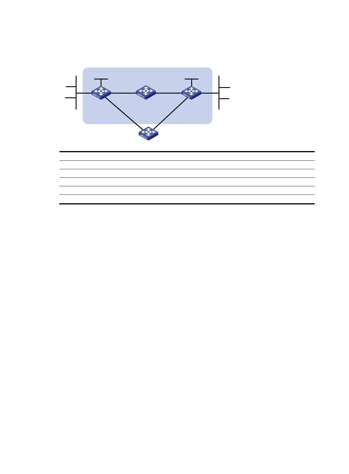
so that when the link between Switch A and Switch B through Switch D fails, BFD can detect the failure
immediately and Switch A and Switch B can communicate through Switch C.
Figure 5 Network diagram
Device Interface IP address
Device
Interface
IP address
Switch A Vlan-int10 12.1.1.1/24 Switch B Vlan-int12 11.1.1.1/24
Vlan-int11 10.1.1.102/24
Vlan-int13 13.1.1.1/24
Loop1 1.1.1.9/32
Loop1
2.2.2.9/32
Switch C Vlan-int11 10.1.1.100/24 Switch D Vlan-int10 12.1.1.2/24
Vlan-int13 13.1.1.2/24
Vlan-int12 11.1.1.2/24
Configuration procedure
1. Configure IP addresses for the interfaces. (Details not shown.)
2. Configure static routes and BFD:
# Configure static routes on Switch A and enable BFD control mode for the static route that
traverses Switch D.
<SwitchA> system-view
[SwitchA] interface loopback 1
[SwitchA-LoopBack1] bfd min-transmit-interval 500
[SwitchA-LoopBack1] bfd min-receive-interval 500
[SwitchA-LoopBack1] bfd detect-multiplier 9
[SwitchA-LoopBack1] quit
[SwitchA] ip route-static 120.1.1.0 24 2.2.2.9 bfd control-packet bfd-source 1.1.1.9
[SwitchA] ip route-static 120.1.1.0 24 vlan-interface 11 10.1.1.100 preference 65
[SwitchA] quit
# Configure static routes on Switch B and enable BFD control mode for the static route that
traverses Switch D.
<SwitchB> system-view
[SwitchB] interface loopback 1
[SwitchB-LoopBack1] bfd min-transmit-interval 500
[SwitchB-LoopBack1] bfd min-receive-interval 500
[SwitchB-LoopBack1] bfd detect-multiplier 9
[SwitchB-LoopBack1] quit
[SwitchB] ip route-static 121.1.1.0 24 1.1.1.9 bfd control-packet bfd-source 2.2.2.9
[SwitchB] ip route-static 121.1.1.0 24 vlan-interface 13 13.1.1.2 preference 65
[SwitchB] quit
# Configure static routes on Switch C.
Switch A Switch B
Switch C
BFD
Vlan-int10
Vl
an-
int1
1
Vlan-int11 Vlan-int13
Vl
an
-
i
nt
13
Vlan-int10
121.1.1.0/24
120.1.1.0/24
Switch D
Vlan-int12
Vlan-int12
Loop1
1.1.1.9/32
Loop1
2.2.2.9/32
 Loading...


