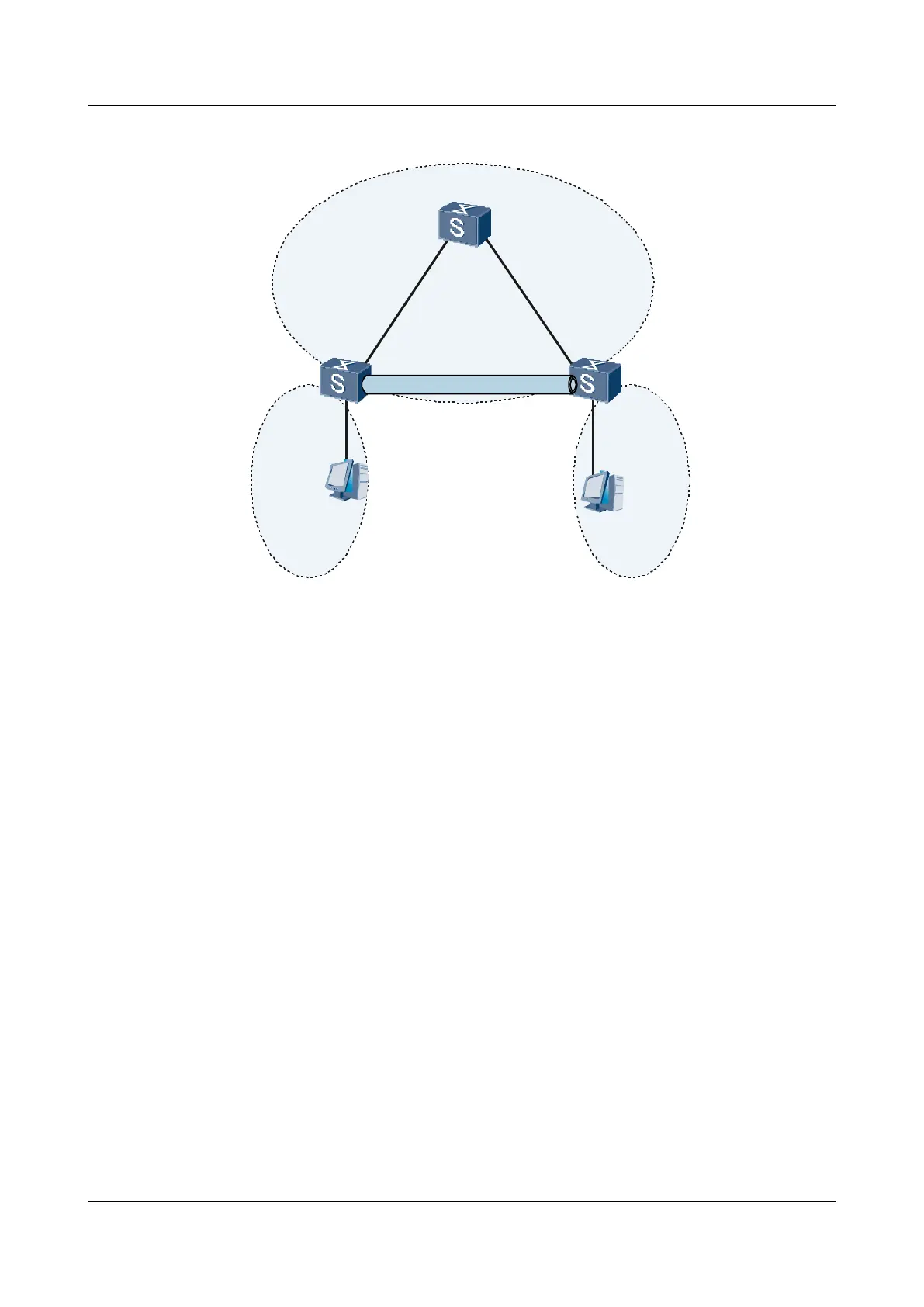
Figure 2-7 Networking diagram for configuring dynamic routing protocol
SwitchA SwitchC
PC1
PC2
Tunnel
GE1/0/0
VLANIF 30
30.1.1.2/24
GE2/0/0
VLANIF 20
20.1.1.1/24
GE1/0/0
VLANIF 10
10.1.1.2/24
GE2/0/0
VLANIF 40
10.2.1.2/24
Tunnel1/0/1
40.1.1.1/24
Tunnel1/0/1
40.1.1.2/24
GE1/0/0
VLANIF 20
20.1.1.2/24
GE2/0/0
VLANIF 30
30.1.1.1/24
SwitchB
OSPF 1
OSPF 2
OSPF 2
10.1.1.1/24
10.2.1.1/24
Device Interface VLANIF interface IP address
Switch A GigabitEthernet1/0/0 VLANIF 10 10.1.1.2/24
GigabitEthernet2/0/0 VLANIF 20 20.1.1.1/24
Switch B GigabitEthernet1/0/0 VLANIF 20 20.1.1.2/24
GigabitEthernet2/0/0 VLANIF 30 30.1.1.1/24
Switch C GigabitEthernet1/0/0 VLANIF 30 30.1.1.2/24
GigabitEthernet2/0/0 VLANIF 40 10.2.1.2/24
Configuration Roadmap
The configuration roadmap is as follows:
1. Run IGP on the Switches (OSPF process 1 is used here).
2. Create GRE tunnels between the Switches connected to PCs so that data between any two
PCs is transmitted through GRE tunnels.
Data Preparation
To complete the configuration, you need the following data:
l IDs of the VLANs that the interfaces belong to, as shown in Figure 2-7
l IP address of the VLANIF interfaces, as shown in Figure 2-7
l Source addresses and destination addresses on the two ends of the GRE tunnel
Quidway S7700 Smart Routing Switch
Configuration Guide - VPN 2 GRE Configuration
Issue 01 (2011-07-15) Huawei Proprietary and Confidential
Copyright © Huawei Technologies Co., Ltd.
80

 Loading...


