EasyManua.ls Logo

Hypertherm ArcGlide Torch Height Control User Manual

Hypertherm ArcGlide Torch Height Control
208 pages
To Next Page IconTo Next Page
To Previous Page IconTo Previous Page
Page #144 background image
4-14 ArcGlide THC Instruction Manual
MAINTENANCE
To update ArcGlide software:
1. After you download the AGUpdater.zip file, unpack it in a directory on the laptop hard drive or on a memory stick.
One of the files included will be “EthernetSetup.vbs”. There will also be some program image .bin files and Update.
exe files to load the images.
2. Plug the laptop into the devices that you want to update
or the Ethernet switch if you want to update multiple
units.
3. Navigate to the directory where you downloaded the
files
4. Double click-on the EthernetSetup.vbs file.
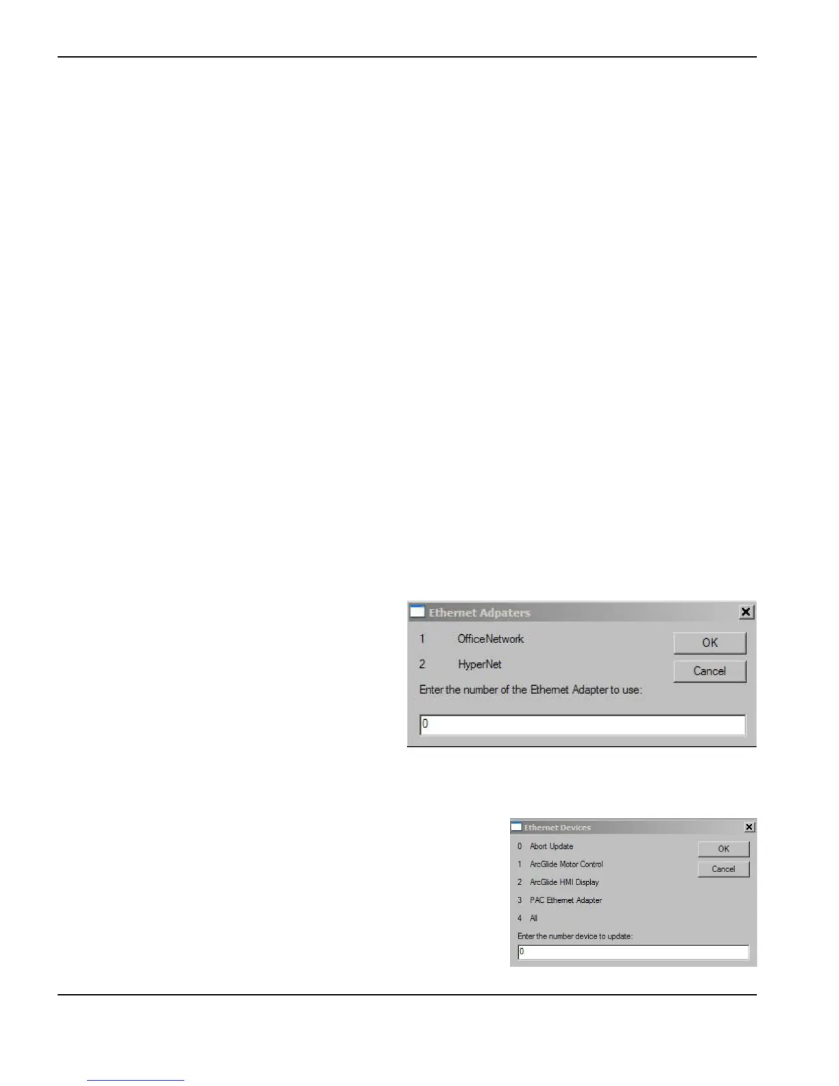
A dialog box displays that lists the Ethernet ports that
are installed on the computer.
5. Enter the number of the adapter that you want to use to
update the ArcGlide unit.
6. After a short delay, a dialog box displays with a list of the devices you can
update.
7. Enter the number of the device that you want to update from the list on
the dialog box.
Select 0 to exit without updating.
8. When the update process is complete, the program returns the network
settings to their original settings and exits.
Update ArcGlide software
Download through Phoenix software
To download software updates for the ArcGlide system using Phoenix software, the ArcGlide must be powered on and
connected to a Hypertherm CNC by Hypernet. You can update directly from the CNC.
To update directly from the CNC:
1. Load the Update.exe file onto a flash drive.
2. Insert the flash drive into the USB port in the CNC.
3. From the Main screen in Phoenix software, select Setups > Password and enter the Special password.
4. On the Special Password screen, press the Update Software softkey.
The CNC updates the Phoenix software and sends ArcGlide software updates to each ArcGlide unit.
Download from a laptop
If your configuration does not include an EDGE Pro CNC or the correct interface with the ArcGlide, you can download
the AGUpdater.zip file from Hypertherm. This file contains the program and script files necessary to update the ArcGlide
components.

Table of Contents

Question and Answer IconNeed help?

Do you have a question about the Hypertherm ArcGlide Torch Height Control and is the answer not in the manual?

Hypertherm ArcGlide Torch Height Control Specifications

General IconGeneral
BrandHypertherm
ModelArcGlide Torch Height Control
CategoryCutter
LanguageEnglish

Summary

SAFETY

RECOGNIZE SAFETY INFORMATION

Symbols identify potential hazards and provide instructions to avoid them.

GROUNDING SAFETY

Proper grounding and earth connections are essential for electrical safety.

ELECTRICAL HAZARDS

Details hazards related to electrical safety and precautions for equipment operation.

ELECTRIC SHOCK CAN KILL

Explains electrical hazards and essential prevention measures during operation.

CUTTING CAN CAUSE FIRE OR EXPLOSION

Provides fire and explosion prevention tips during cutting operations.

COMPRESSED GAS EQUIPMENT SAFETY

Guidelines for safe handling and use of compressed gas cylinders and equipment.

TOXIC FUMES CAN CAUSE INJURY OR DEATH

Discusses risks associated with toxic fumes and mitigation strategies.

A PLASMA ARC CAN CAUSE INJURY AND BURNS

Highlights risks of plasma arcs causing physical injury and burns.

ARC RAYS CAN BURN EYES AND SKIN

Details protection measures against arc rays for eyes and skin.

PACEMAKER AND HEARING AID OPERATION

Addresses potential effects of magnetic fields on pacemakers and hearing aids.

NOISE CAN DAMAGE HEARING

Information on noise hazards and hearing protection measures.

DRY DUST COLLECTION INFORMATION

Discusses potential explosion hazards from dry dust and relevant standards.

LASER RADIATION

Explains risks of laser radiation and safety precautions.

ADDITIONAL SAFETY INFORMATION

Lists various ANSI, AWS, NFPA, and other relevant safety standards.

PRODUCT STEWARDSHIP

Introduction

Outlines Hypertherm's global regulatory management system for product compliance.

National and local safety regulations

Emphasizes precedence of local regulations over manual instructions for installation and use.

Certification test marks

Explains identification and meaning of certification test marks on products.

Differences in national standards

Highlights how national standards may vary, affecting product compliance.

Safe installation and use of shape cutting equipment

Provides guidance on safe installation and operation per IEC 60974-9.

Procedures for periodic inspection and testing

Details requirements for periodic inspection and testing of electrical safety.

Qualification of test personnel

Specifies requirements for personnel performing electrical safety tests.

Residual current devices (RCDs)

Discusses the use and selection of RCDs in certain countries for electrical safety.

Higher-level systems

Addresses considerations for integrated systems combining Hypertherm products with other equipment.

ENVIRONMENTAL STEWARDSHIP

Introduction

Outlines Hypertherm's commitment to environmental specifications and supplier information.

National and local environmental regulations

Emphasizes compliance with national and local environmental regulations for product lifecycle.

The RoHS directive

Explains Hypertherm's compliance with the EU Restriction of Hazardous Substances Directive.

Proper disposal of Hypertherm products

Guides on environmentally responsible disposal of electronic products and components.

The WEEE directive

Discusses the EU Waste Electrical and Electronic Equipment Directive and recycling criteria.

The REACH regulation

Details Hypertherm's compliance with the EU REACH regulation concerning chemicals.

Proper handling and safe use of chemicals

Addresses requirements for Material Safety Data Sheets (MSDS) for chemicals used.

Fumes emission and air quality

Provides general information on air quality, NIOSH methods, and testing.

SPECIFICATIONS

Introduction

Introduces the ArcGlide THC system and its components.

Control module

Describes the microcontroller, I/O interface, and motor drive unit.

Lifter assembly

Details the torch lifter station and its features for positioning the torch head.

Human machine interface (HMI)

Explains the HMI functions including setup, parameters, and operation.

Plasma interface

Describes the functions and types of plasma interfaces for voltage feedback.

Industrial Ethernet switch

Specifies the requirement for an Ethernet switch in multi-span Hypernet configurations.

Specifications

Presents detailed specifications for the system, control module, and other components.

System

Lists general system specifications like input power, temperature, and warranty.

Control module (090054)

Provides specific technical details and dimensions for the control module.

Lifter assembly (090053)

Details specifications for the lifter assembly, including parts and mounting options.

Optional HMI (090055)

Details specifications and dimensions for the optional HMI unit.

Discrete plasma interface (090052)

Outlines electrical specifications for the discrete plasma interface.

Ethernet switch

Explains the need for an Ethernet switch and lists required ports.

Ethernet connectors

Specifies the type of Ethernet connectors used.

Electrical protection

Details electrical protection features for Ethernet connections.

I/O transmission distance

Specifies the maximum allowed transmission distance for I/O signals.

I/O transmission speed

States the transmission speed for I/O signals.

Operating temperature

Provides the operating temperature range for Ethernet switches.

ArcGlide communication

Illustrates discrete and Hypernet communication styles and their cabling.

Hypernet communication configurations

Explains Hypernet connections to CNC and plasma systems via Ethernet cables.

Discrete communication configurations

Details signal routing via control module using discrete cables.

Mixed communication configurations

Describes configurations using both Hypernet and discrete links.

INSTALLATION

Hardware setup

Outlines initial steps for setting up the hardware components of the system.

Upon receipt

Instructions for verifying received components and checking for shipping damage.

Claims

Procedures for filing claims for damaged or missing merchandise.

Installation requirements

Specifies that installation must conform to national/local codes and be by qualified personnel.

Placement of system components

Guidance on positioning system components and grounding them to earth.

Recommended grounding and shielding practices

Details necessary grounding and shielding to protect against RFI/EMI noise.

Introduction

Introduces grounding and shielding necessities for plasma cutting systems.

Types of grounding

Describes three types of grounding systems: safety, DC power, and RFI/EMI.

Steps to take

Provides a step-by-step guide for implementing grounding and shielding practices.

RFI and EMI Grounding

Explains grounding for limiting electrical noise from plasma and motor drive systems.

System description for a Hypernet configuration

Illustrates cable and signal connections for Hypernet configurations.

System description for a discrete configuration

Illustrates cable and signal connections for discrete configurations.

Configuration examples

Provides examples of various ArcGlide THC configurations and connections.

Install the lifter

Provides mounting dimensions and instructions for installing the lifter.

Connect the Ohmic wire to HPR XD plasma systems

Details connecting the Ohmic wire for HPR XD plasma systems.

Connect the Ohmic wire to other plasma systems

Instructions for connecting the Ohmic wire to non-HPR XD plasma systems.

Ground the lifter

Explains the procedure for properly grounding the lifter assembly.

Install the control module

Provides instructions for mounting the control module.

Ground the control module

Outlines the steps for grounding the control module.

Install the optional HMI

Guides on the installation process for the optional HMI.

Ground the HMI

Details how to properly ground the HMI unit.

Connect Hypernet cables

Instructions for connecting Hypernet cables, requiring an Ethernet switch.

Connect discrete cables

Provides guidance on connecting discrete cables for various system configurations.

Cables

Introduces the section detailing different types of cables used in the system.

Lifter interface cable

Details the lifter interface cable, including part numbers and pinouts.

Hypernet and HMI interface cable

Describes the Hypernet and HMI interface cable, including pinouts.

Operator console I/O cable

Details the operator console I/O cable, including pinouts and dry contact circuits.

ArcGlide motor control CNC interlock kit (228594)

Explains the interlock kit for enabling/disabling Z-axis motion.

CNC I/O cable

Details the CNC I/O cable, pinouts, and circuit types.

Plasma interface I/O cable

Details the plasma interface I/O cable, including pinouts and signal descriptions.

Non-serial plasma interface cable

Describes the non-serial plasma interface cable for specific HPR models.

Serial plasma interface cable

Details the serial plasma interface cable for serial communication.

ArcGlide discrete interface signal examples

Provides examples of discrete interface signal schematics for inputs and outputs.

Inputs

Explains input modes (dry contact, sourced) and their selection.

Outputs

Describes the relay contact outputs and their protection.

CNC discrete I/O

Details required and optional discrete interface signals between CNC and control module.

Plasma discrete I/O

Details discrete interface signals between plasma system and control module.

Optional operator console discrete I/O

Lists discrete signals used between control module and operator console.

ArcGlide software setup

Guides on setting up ArcGlide software with Hypertherm CNC and Hypernet.

ArcGlide axes

Explains how to verify and set up ArcGlide axes parameters.

ArcGlide THC ports

Details how to assign ports for ArcGlide THCs in the Machine setup screen.

ArcGlide setup parameters

Lists and explains various setup parameters for ArcGlide.

OPERATION

Operator controls

Details the controls available on the system components.

Control module

Explains the operator controls on the control module.

Lifter

Describes the controls and status indicators on the lifter assembly.

HMI

Details the HMI controls, LEDs, and display functions.

Daily operations

Covers essential daily tasks like startup and shutdown procedures.

Startup procedure

Outlines the sequence for powering on the entire cutting system.

Shutdown procedure

Explains how to properly power down the ArcGlide THC and the system.

ArcGlide THC operating modes

Describes the manual and automatic operating modes of the ArcGlide THC.

Manual mode

Details how to operate the ArcGlide THC in manual mode and its uses.

Automatic modes

Explains the three automatic operating modes for production cutting.

Arc voltage control (AVC) disabled

Describes the simplest automatic mode with fixed torch height.

Set arc voltage mode

Explains operating in Set Arc Voltage mode for specific cutting conditions.

Sampled arc voltage mode

Details the most automatic mode, using sampled arc voltage for control.

Operating the HMI

Guides on using the HMI for control, parameter setting, and diagnostics.

HMI screen hierarchy

Provides an overview of the HMI's screen structure and navigation.

Main parameters

Explains the primary display parameters seen during normal operation.

Setup parameters

Details the parameters available for system setup and maintenance.

Diagnostics screen

Describes the Diagnostics display for error and control state information.

Installation screen

Provides access to lifter specifications and control module parameters.

Manual Mode

Details information displayed in manual mode, including errors and pierce delay.

Lifter Disabled Mode

Explains parameters displayed when the lifter is disabled.

ArcGlide operating parameters

Details parameters that determine ArcGlide THC operation with a Hypertherm CNC.

ArcGlide setup parameters

Lists and explains various setup parameters for ArcGlide.

MAINTENANCE

Introduction

Assumes service personnel are qualified technicians for troubleshooting.

Lifter routine maintenance

States control module and HMI require no routine maintenance.

Carriage

Details lubrication intervals for the carriage based on operation hours.

Sealing strip

Mentions the sealing strip needs oiling at lubrication intervals.

Cable connections

Recommends checking cables for chafing or damage, especially the Ohmic wire.

System grounding

Verifies grounding of system components to earth ground.

Flow of ArcGlide operations

Illustrates the sequence of states in ArcGlide THC operation.

Common cutting faults

Lists common cutting faults and their possible causes.

How to optimize cut quality

Provides tips and procedures for achieving square, straight, smooth cuts.

Plasma set-up tips

Advises following operating cycle steps and purging gas lines before cutting.

Maximize the life of consumable parts

Explains the LongLife process for minimizing consumable erosion.

Additional factors of cut quality

Discusses factors affecting cut quality like cut angle and dross.

Cut angle

Defines acceptable cut angles and how to diagnose issues.

Dross

Explains causes of low-speed and high-speed dross and how to reduce it.

Straightness of the cut surface

Addresses cut surface concavity/convexity and corrective actions.

Additional improvements

Mentions trade-offs involved in certain improvements.

Piercing

Discusses pierce delay, Pierce Complete signal, and factors affecting piercing.

How to increase cutting speed

Suggests decreasing torch-to-work distance to increase cutting speed.

Update ArcGlide software

Guides on updating ArcGlide software via Phoenix or laptop.

Download through Phoenix software

Instructions for updating software directly from the CNC.

Download from a laptop

Details downloading software updates using a laptop.

Operator tests

Explains how operators can perform tests for lifter mechanics and IHS.

Problems and solutions

Provides a table of common problems and their solutions.

Unable to establish communication with the CNC or plasma system.

Troubleshooting steps for communication loss between CNC/plasma and ArcGlide.

No response to CYCLE-START-IN at THC.

Steps to diagnose lack of response to CYCLE-START-IN signal.

Arc ignites before IHS is complete.

Troubleshooting steps when the arc ignites before IHS completion.

The green Enable light on the lifter is not illuminated.

Refers to installation section for troubleshooting the Enable light.

The torch does not approach workpiece at programmed IHS speed and stall force.

Steps to diagnose torch not approaching workpiece correctly during IHS.

Inaccurate IHS with nozzle ohmic contact.

Troubleshooting steps for inaccurate IHS with nozzle ohmic contact.

Inaccurate IHS with Stall Force sensing.

Troubleshooting steps for inaccurate IHS with stall force sensing.

Torch fails to ignite.

Steps to diagnose why the torch fails to ignite.

Torch arc fails to transfer to workpiece.

Troubleshooting steps when the torch arc fails to transfer.

Arc extinguishes immediately after transfer or creates an excessively large pierce hole.

Diagnoses issues causing arc extinguishment or large pierce holes.

The laser pointer is not illuminated

Troubleshooting steps when the laser pointer is not illuminated.

Torch moves before workpiece is pierced all the way through.

Diagnoses why the torch moves before piercing is complete.

Torch dives below cutting height immediately after pierce delay and before AVC begins.

Troubleshooting steps for torch diving below cutting height.

Torch dives toward workpiece immediately after AVC begins.

Steps to address torch diving towards workpiece after AVC begins.

Torch retracts from workpiece immediately after AVC begins.

Troubleshooting steps for torch retracting prematurely after AVC begins.

Retract begins before arc has extinguished.

Suggests increasing Retract Delay if retraction starts before arc extinguishes.

Failure to retract

Steps to troubleshoot failure to retract, including Homing Speed.

Troubleshooting routines

Offers systematic approaches to troubleshooting common issues.

Edge Pro will not communicate with HPR power supply

Troubleshooting steps for communication issues between Edge Pro and HPR.

Error message troubleshooting

Explains how to troubleshoot error messages displayed on HMI and control module.

Printed circuit board (PCB) block diagrams

Shows block diagrams of PCBs for system configurations.

ArcGlide PCBs

Lists the various Printed Circuit Boards (PCBs) associated with the ArcGlide system.

HMI processor (228581)

Details the HMI processor PCB, including test points and connectors.

HMI Processor PCB

Details the HMI processor PCB, including connectors and signals.

HMI 7-segment display interface (228582)

Describes the HMI 7-segment display interface PCB.

THC controller interface (228577)

Details the THC controller interface PCB, including connectors and pinouts.

THC processor (228578)

Describes the THC processor PCB and its unit address switch.

J1 Board interconnects (continued)

Lists continued pinouts for J1 Board interconnects.

J4 Lifter interface

Details pin assignments for the J4 Lifter interface.

J5 Plasma interface

Details pin assignments for the J5 Plasma interface.

J6 CNC interface

Details pin assignments for the J6 CNC interface.

J7 Op-Con interface

Details pin assignments for the J7 Op-Con interface.

Discrete plasma interface (228576)

Details the discrete plasma interface PCB and its LEDs.

J1 Plasma interface

Details pin assignments for the J1 Plasma interface.

J2 (+24 V or contact closure inputs to the THC from a generic plasma system)

Details J2 pin assignments for generic plasma system inputs.

J3 (Relay contact outputs from the THC to a generic plasma system)

Details J3 pin assignments for generic plasma system outputs.

J4 Arc voltage

Details J4 pin assignments for arc voltage measurement.

J5 Plasma I/O cable (blue)

Details pin assignments for the J5 Plasma I/O cable.

Hypernet plasma interface (141161)

Describes the Hypernet plasma interface PCB and its unit address switch.

J5 CNC interface

Details pin assignments for the J5 CNC interface.

J6 Remote ON/OFF

Details pin assignments for the J6 Remote ON/OFF control.

Lifter interface (228580)

Details the lifter interface PCB and its various switches and connectors.

PARTS LIST

Lifter parts

Lists and illustrates the individual parts for the lifter assembly.

THC controller parts

Lists and illustrates the individual individual parts for the THC controller.

HMI parts

Lists and illustrates the individual parts for the HMI.

Plasma interface PCB

Lists and illustrates the plasma interface PCB.

WIRING DIAGRAMS

Introduction

Explains the section contains wiring diagrams and referencing format.

Wiring diagram symbols

States that symbols and their identification precede the wiring diagrams.

Wiring diagram symbols

Illustrates and identifies common electronic and electrical symbols used in diagrams.

Torch Symbols

Illustrates symbols representing torch components like electrode, nozzle, and shield.

Sheet 1 of 4

Represents the first sheet of the wiring diagrams.

Sheet 2 of 4

Represents the second sheet of the wiring diagrams.

Sheet 3 of 4

Represents the third sheet of the wiring diagrams.

Sheet 4 of 4

Represents the fourth sheet of the wiring diagrams.

Related product manuals