2-40 ArcGlide THC Instruction Manual
INSTALLATION
2
Notes:
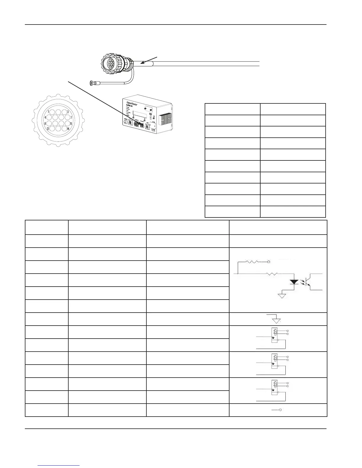
• Input signals (pins 2 – 6) use 24 VDC; Output signals (pins
8 – 14) use dry contact closures at 24 VDC.
• For more information about discrete operator console I/O
signals, see ArcGlide discrete interface signals.
* Pin numbers are the same on both ends of the cable.
Part number Length
223216 3.0 m (10 ft)
223217 6.0 m (20 ft)
223121 7.5 m (25 ft)
223218 10.5 m (35 ft)
223006 15.0 m (50 ft)
223111 23.0 m (75 ft)
223112 30.5 m (100 ft)
223113 45.5 m (150 ft)
223114 61.0 m (200 ft)
Operator console I/O cable
Green band
Connect this end to
the connector on the
control module with
the green circle.
Add the appropriate
connector for your
console on this end.
Contact your console
supplier for additional
information.
Pin number* Color Signal name Dry contact circuit
1 Black Not connected
2 White Manual disable switch input +
3 Red Manual select switch input +
4 Green Torch up switch input +
5 Orange Torch down switch input +
6 Blue Spare switch input +
7 White/black Common
8 Red/black Torch enabled output A
9 Green/black Torch enabled output B
10 Orange/black Error output A
11 Blue/black Error output B
12 Black/white Spare output A
13 Red/white Spare output B
14 Green/white Power +24 VDC output
3.9 K
3.9 K
+24 V
A
B
A
B
A
B
+24 V
normally
open
normally
open
normally
open