ArcGlide THC Instruction Manual 2-23
A
17
18
INPUT 12
OUTPUT 10
OUTPUT 11
OUTPUT 12
5
7
1
26
25
INTERLOCK
12
32
31
30
MOTION
CYCLE START
AVC DISABLE
IHS SYNC
24V COMMON COMMON
31
24V
PULL UP
24V
PULL UP
24V
PULL UP
CYCLE START
RELAY
RELAY
BREAKAWAY
BREAKAWAY
37
11
INPUT 11
22
21
COMMON
JUMPER
JUMPER
COMMON
29
30
TORCH
B
D S D S
CNC PLASMA
INPUT
24V
+24V
+24V
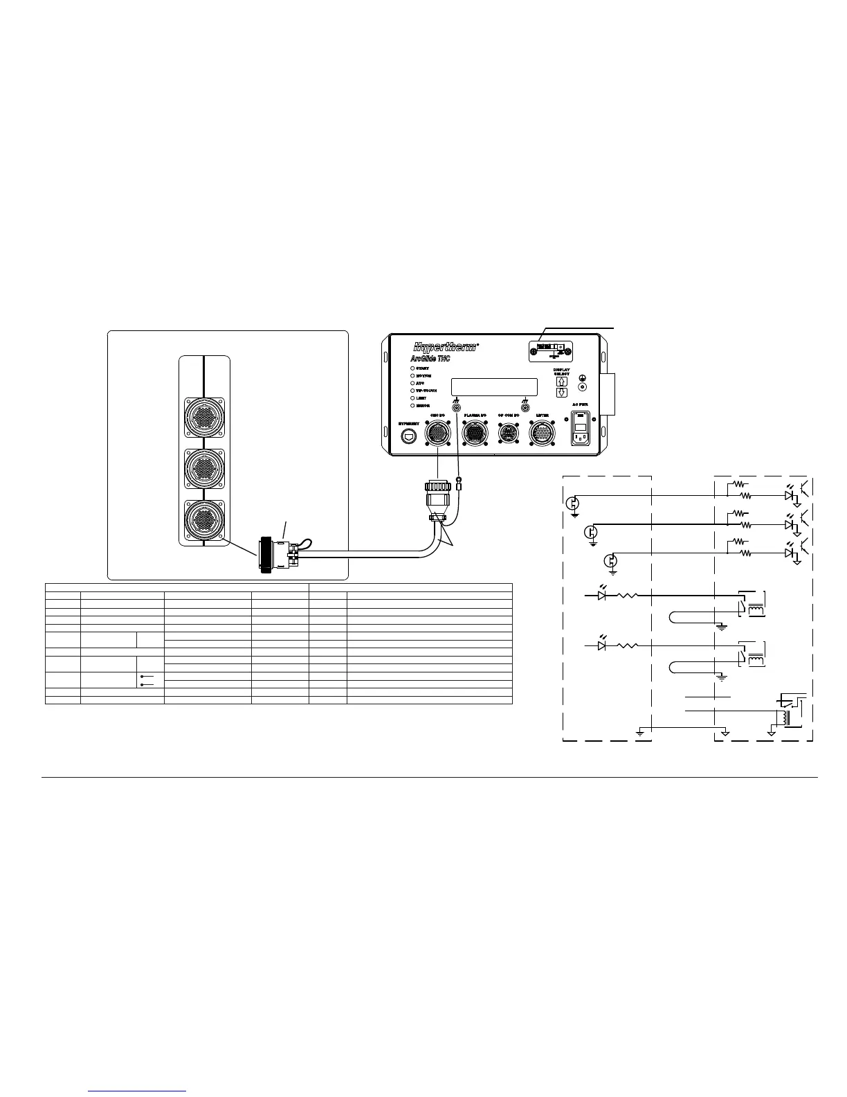
ArcGlide CNC interface with discrete connection to a Picopath CNC
ArcGlide control
module
Set dry contacts by sliding
the switch to D.
ArcGlide CNC
interface cable
CNC with Picopath interface
Picopath connector kit
(228490)
Axes 3, 4
Axes 1,2
I/O
Picopath CNC end A
ArcGlide control module end B
Picopath CNC end (A), terminated during installation ArcGlide end (B), terminated by Hypertherm
Pin Function Phoenix mapping name Wire color Pin Signal
32 Output 12 Cut control Red 1 Cycle start input+
31 Output 11 Hold ignition Blue 7 IHS sync input+
30 Output 10 Torch height disable Green 5 AVC disable input +
12 Input 12 Cut sense 1 Green 17 Machine motion output A
Jumper together
⊂
Red 18 Machine motion output B
Blue 29 Common
11 Input 11 Torch collision Yellow 21 Torch breakaway output A
Jumper together
⊂
Red 22 Torch breakaway output B
Green 30 Common
External switch
Orange 25 Interlock input+
Red 26 Interlock input -
37 24 V Common Yellow 31 Common
Backshell Ground Ground
• Start with Hypertherm-supplied ArcGlide CNC interface cable and terminate the Picopath end.
• This example uses CNC outputs 10, 11, 12, and inputs 11 and 12. Map I/O in Phoenix software accordingly.
• Multiple wires are the same color. Verify pin-to-pin connections before plugging cables into equipment.
• Incorrect wiring can cause permanent damage to Picopath or ArcGlide circuits.
• Set ArcGlide CNC inputs to dry with the slide switch on the control module.
• ArcGlide interlock must be satisfied (closed) to enable ArcGlide motion.
2