Powermax30 AIR Service Manual 808850 147
6 – Power Supply Component Replacement
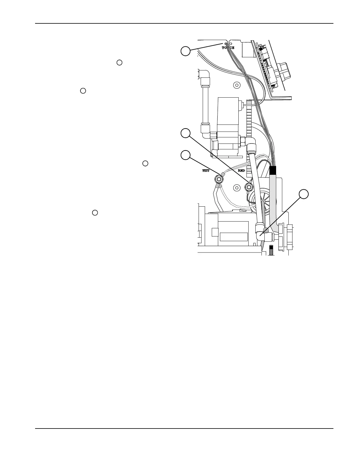
4. Facing the fan side of the power supply,
slide the ring terminal for the bundle of
3 white wires over the left stud (labeled
“WHT” on the center panel) .
5. Slide the ring terminal for the red wire onto
the stud on the right (labeled “RED” on the
center panel) .
Also put back in place any other wires
you removed from the WHT and RED
studs.
6. Use an 8 mm (5/16 inch) nut driver to
tighten the nut on each stud to 23.0 kg∙cm
(20 inch∙pounds).
7. Push-to-connect the plastic 90° fitting
onto the new torch lead’s brass gas supply
fitting.
8. Route the orange, blue, and purple wire
group over the center panel. Position the
wires in the notch in the panel that is
labeled “TORCH” .
9. Press the connector into the TORCH
START slot (J12) on the power board. See
Figure 61 on page 145.
10. Tighten the torch lead’s strain relief nut onto
the strain relief as you put the front panel
back in place. See Reattach the front panel
on page 103.
11 . Complete the following procedures:
a. See Install the power supply cover on page 99.
b. Reconnect the power cord, and set the power switch to ON (I).
 Loading...


