Service Procedures for the PCBs and Related Components
Powermax65/85 SYNC Service Parts and Procedures 810440 99
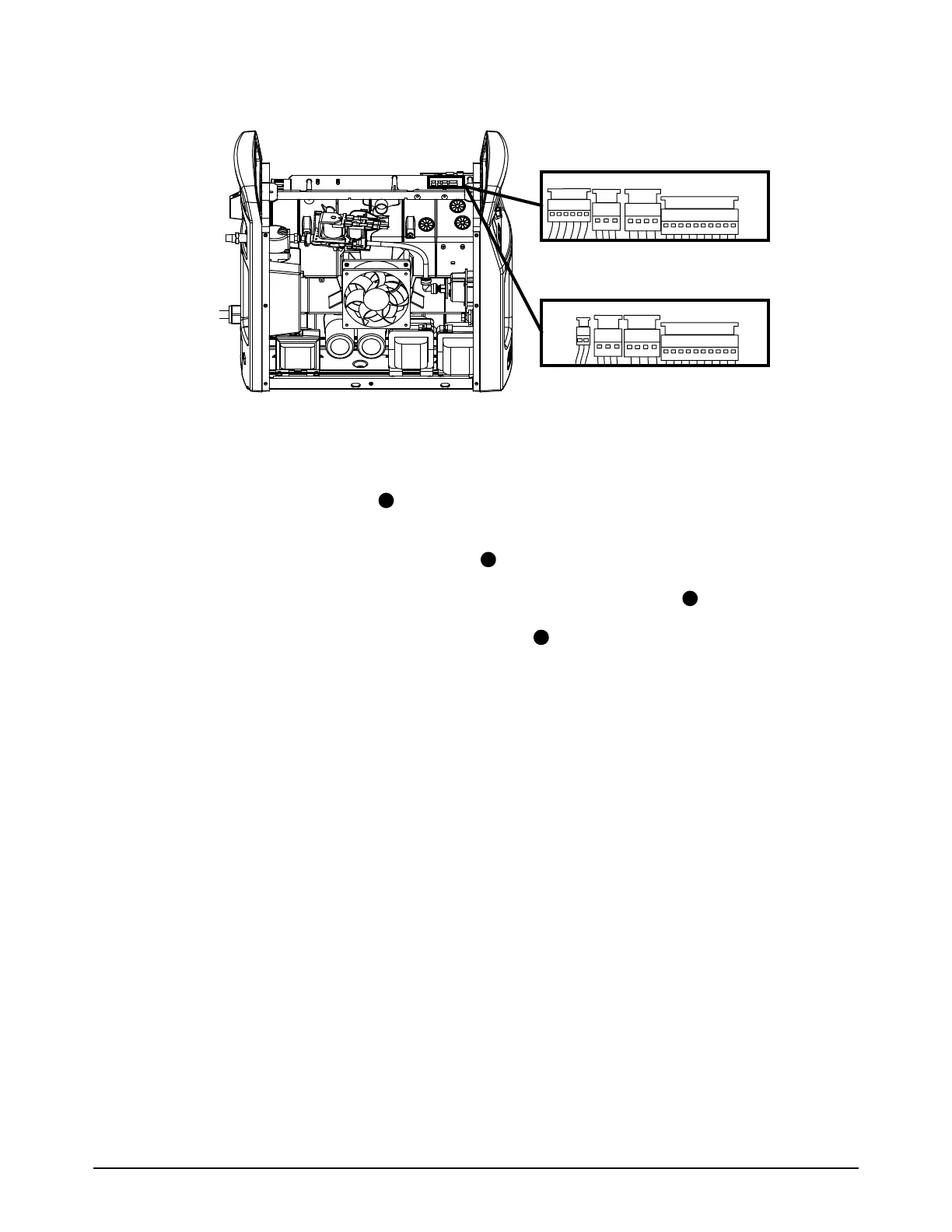
6. Disconnect the 4 wire connectors near the top of the power PCB.
For step 7 through step 15, refer to Figure 1 and Figure 2.
7. Remove the 3 µF capacitors from near the center of the power PCB. The number of
capacitors is different for each system. Set aside the capacitors and the screws.
8. Disconnect the gate drive wire connectors .
9. CSA models: Disconnect the PFC temperature sensor wire connector .
10. CE/CCC models: Disconnect the MOV assembly from the right side of the power PCB. Set
aside the MOV assembly and the screws.
11 . Remove all of the remaining screws that attach the power PCB to the heatsink components and
to the center panel. Make sure that you identify where the screws go so that you know where to
install them on the new power PCB.
12. Disconnect the J12 and J20 connectors from the left side of the power PCB.
13. If you are using a machine interface connection, disconnect the J21 and J32 (CSA) or J33
(CE/CCC) connectors from the left side of the power PCB.
14. Pull the right edge of the power PCB forward, and push the gate drive wires and PFC
temperature sensor wire through the openings in the PCB.
15. Carefully remove the power PCB and set it aside in an anti-static bag.