2. If a 2 pin jumper is installed on a 2 pin connector then+5Vdcisenabled to pin 18.
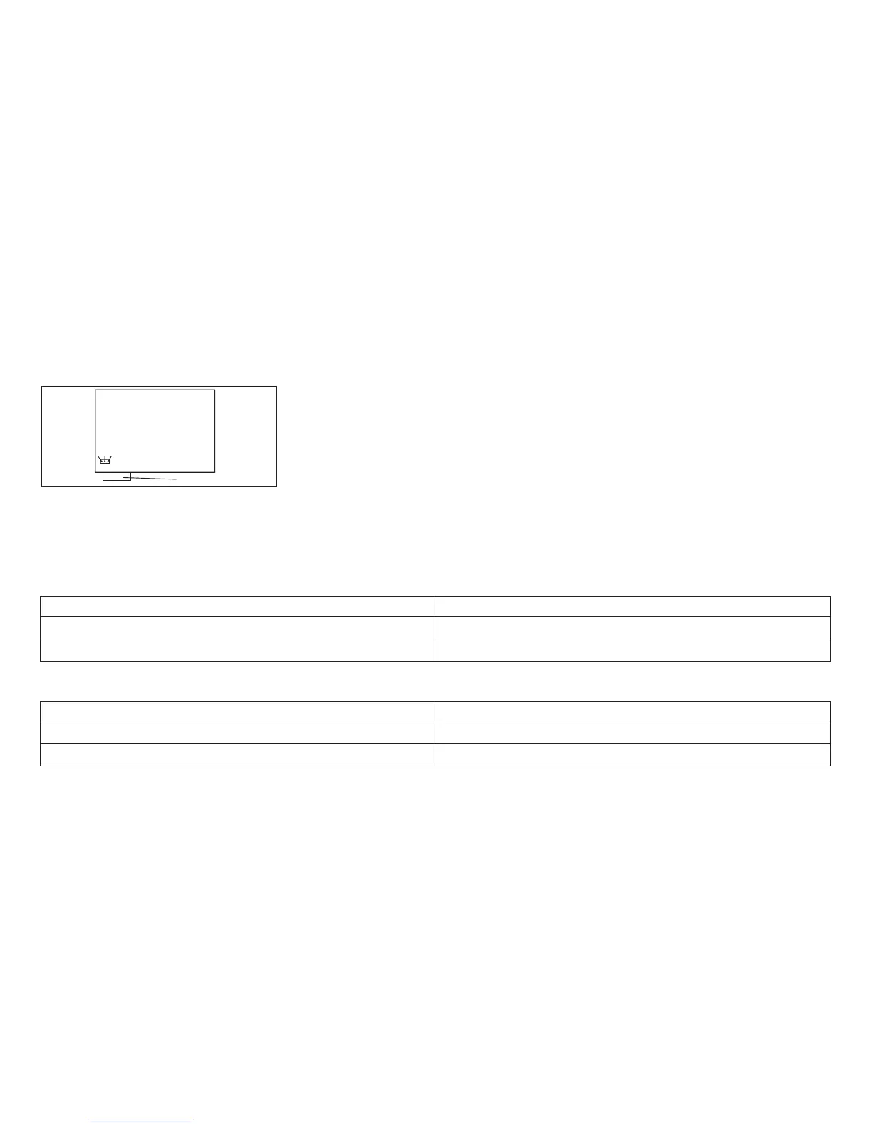
3. If a 2 pin jumper is installed on a 3 pin connector, as shown in Figure 47, use the chart below and verify the
jumper is installed to enable +5 V dc on pin 18. If the jumper is not installed correctly, move it to the pins
shown in the chart.
Note: If after installing the logic board, the NPS 540+ power light is not lighted, check for+5Vdconpin18with
a volt meter (pin 18 is shown on connector).
Table 43. Model A00 logic board jumper location to enable +5 V dc on pin 18:
4247 A00 Logic Board Level Install jumper between pins
Level1,2,3logic board 2 and 3
Level 4 logic board 1 and 2
Table 44. Models 001 and 002 logic board jumper location to enable +5 V dc on pin 18:
4247 001, 002 Logic Board Level Install jumper between pins
Level1,2,logic board 2 and 3
Level 3 logic board 1 and 2
123
Logic Board
Parallel Connector
Figure 47. Models A00, 001, and 002 Pin 18 +5V Jumper Location.
(Viewed From Rear)
Chapter 4. Locations 274