Note: If after installing the logic board, the NPS 540+ power light is not lighted, check for+5Vdconpin18
with a volt meter (pin 18 is shown on connector).
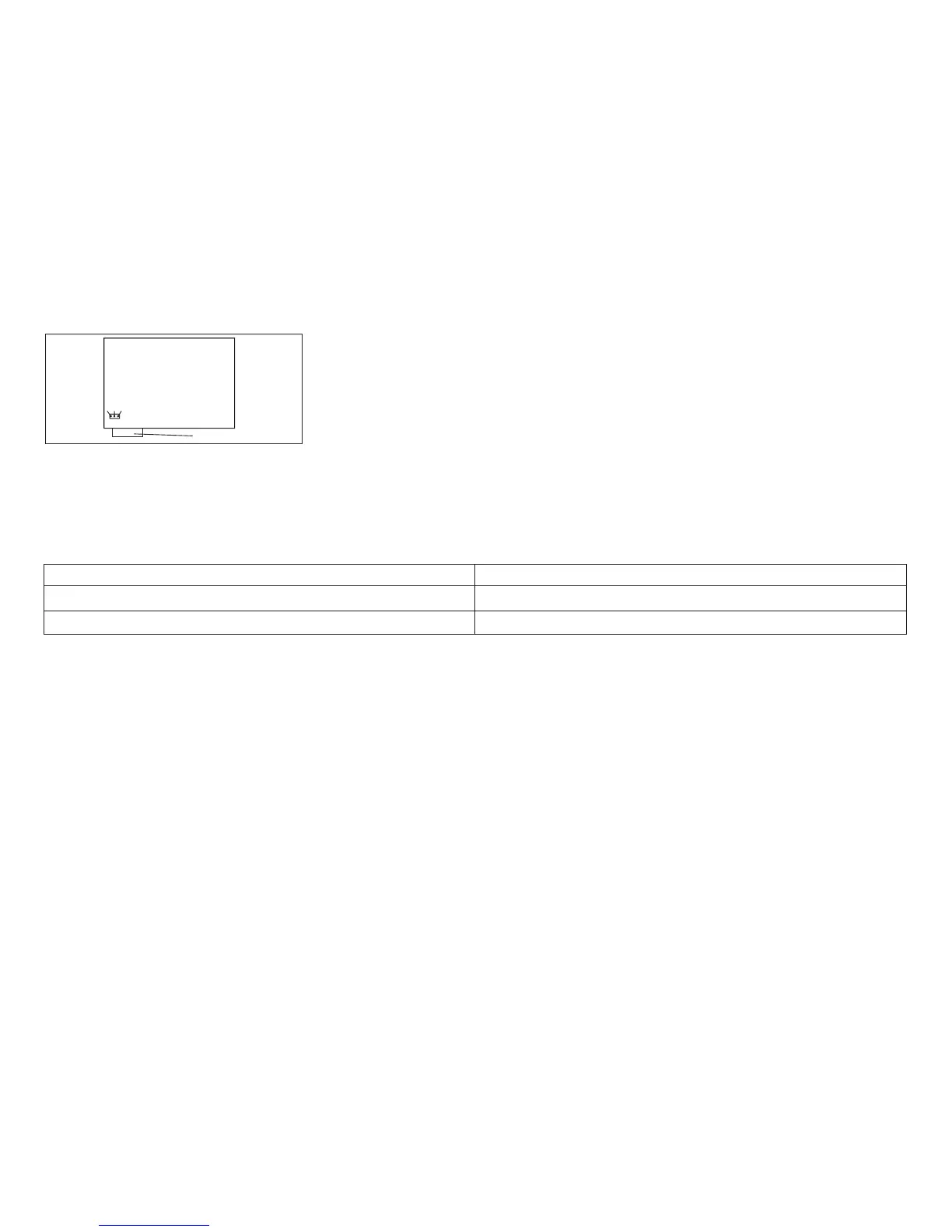
Table 51. Model A00 logic board jumper location to enable +5 V dc on pin 18:
4247 A00 Logic Board Level : Install jumper between pins:
Level1,2,3logic board 2 and 3
Level 4 logic board 1 and 2
4. Run the T&D program in automatic mode.
For Model A00, see “How To Run the Test and Diagnostic (T&D) Programs” on page 161.
For Models 001 and 002, see “How To Run the Test and Diagnostic (T&D) Programs” on page 201.
Ensure that T&D11, T&D12, T&D15, T&D16, and T&D17 are adjusted, if indicated.
5. Use the configuration setup printout to configure the printer. See
IBM 4247 Printer Model A00 User’s Guide
.
EMI Filter (Model A00 Early-Level Logic Board Only)
Removal
Attention: The electronic parts of this printer can be damaged by electrostatic discharge (ESD). Ensure that ESD
protection devices and procedures, including a static discharge wrist strap, are used while working on the printer.
1. Power off (O) the printer and disconnect the power cord from the customer outlet.
2. Put the covers in the service position. See “Removing Covers” on page 275.
123
Logic Board
Parallel Connector
Figure 118. Model A00 Logic Board Jumper Location.
(Viewed From Rear)
Chapter 5. Removals and Adjustments 377