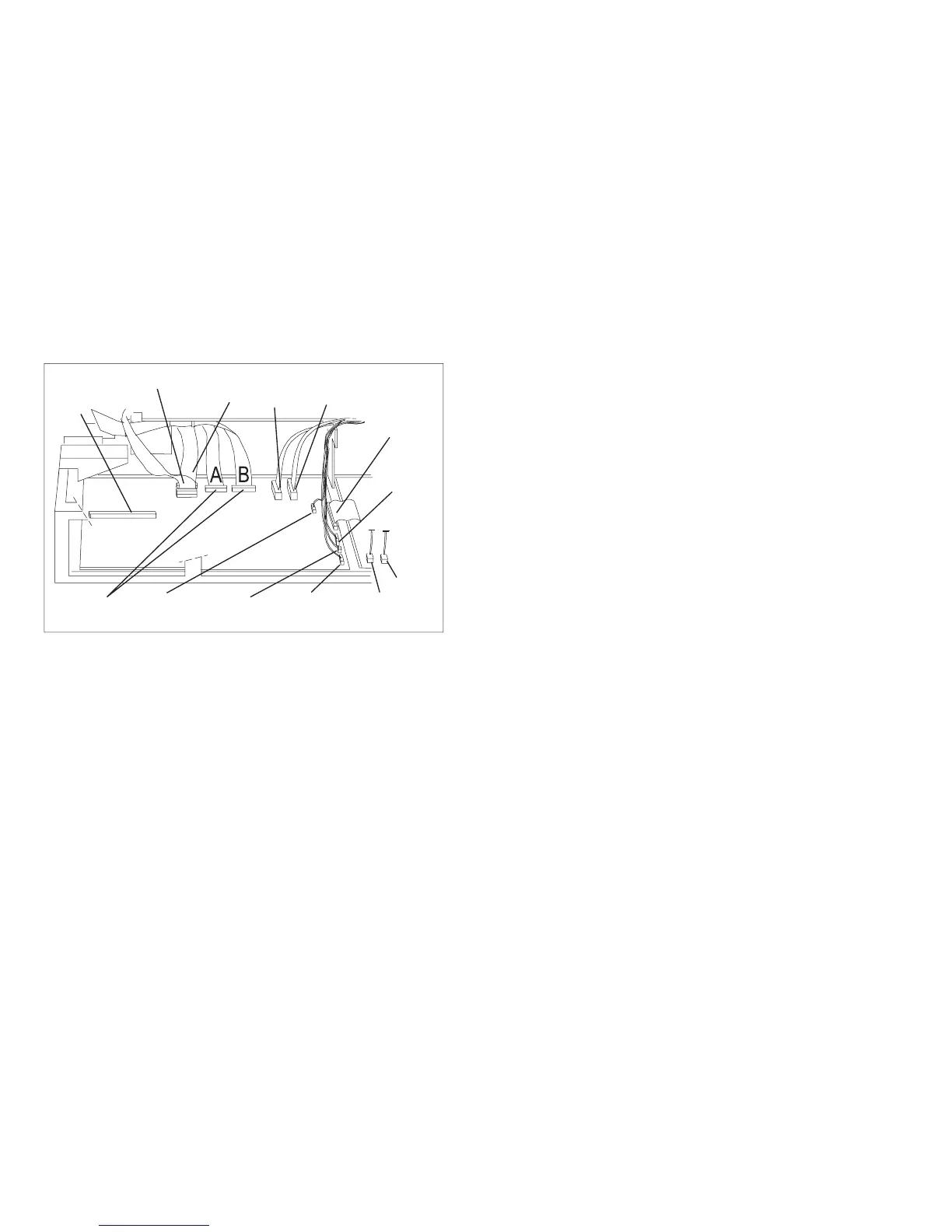
Connector Locations - Model 003
Network Print Server Attachment Pin 18 +5 V Jumper Location and the
Parallel Connector
The NPS Ethernet 540+ can be used without an external power supply only if +5 V dc is enabled (supplied) on
pin 18 of the printer parallel attachment connector. NPS devices (p/n 30H4082, 30H4083, 30H4055) cannot be
powered by pin 18 and always require an external +12 V ac power supply. There is no danger of damaging any
NPS or other computer devices when +5 V dc is enabled on pin 18. The new logic board you receive will have a
2 pin jumper installed on either a 2 pin or a 3 pin connector located near the parallel attachment connector.
1. Find the 2 pin jumper and connector
Operator
Panel
ASF
Stacker
Attachment
Connector
Tractors
Sensors
(Path, Ribbon Motion
and Carriage Home)
Print Head
and Ribbon
Lift Motor
Board
Fan
Power
Supply
Carriage
Motor
AFTA
Ribbon Driver
Motor
Paper
Feed
Motor
Carriage
Fan
E90ALOCA
Figure 46. Connector Locations - Model 003
Chapter 4. Locations 273