Attachment Card Procedure 2
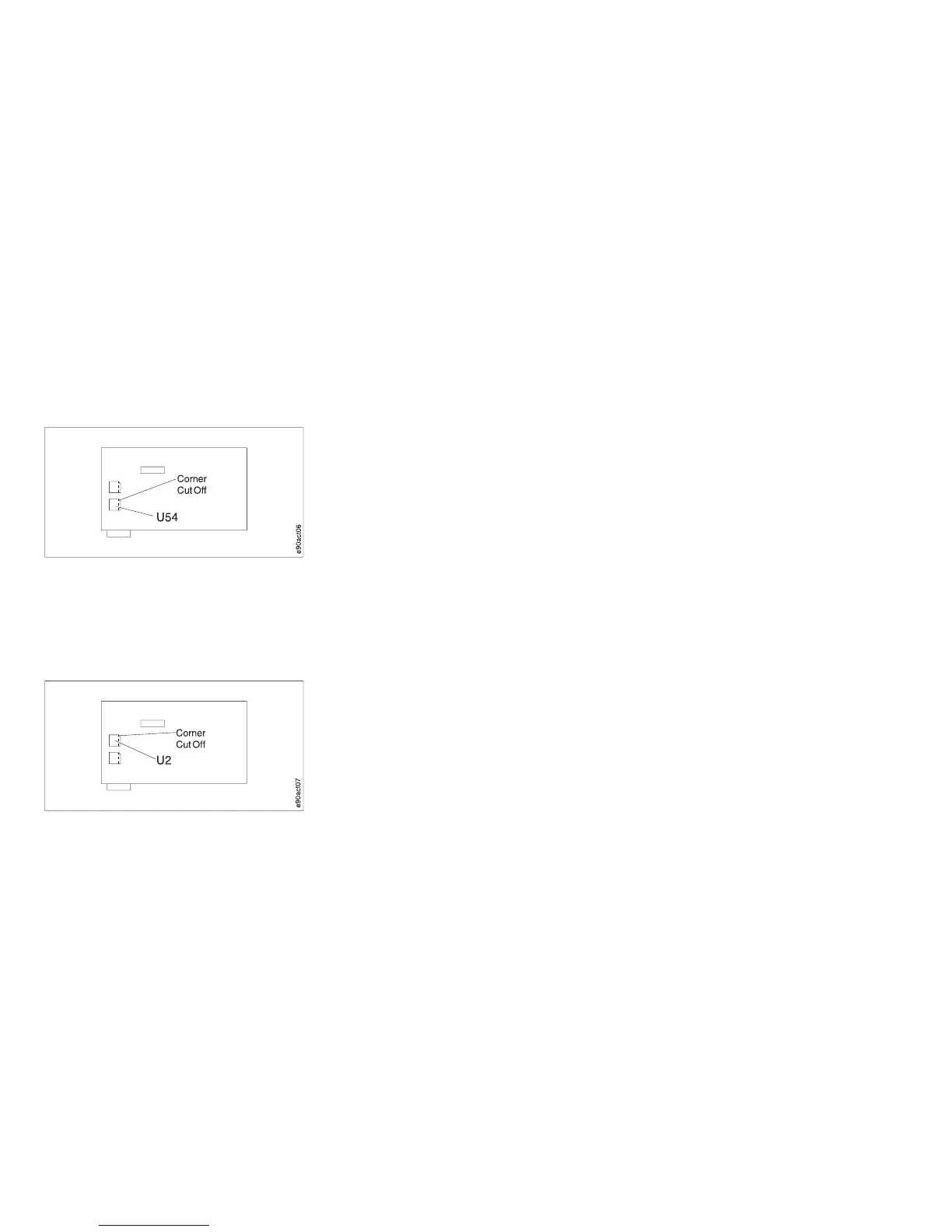
Figure 8 shows the location and orientation of the Model 001 (early-level) and the Model 002 logic board controller
microcode module U54.
Figure 9 shows the location and orientation of the Model 001 (early-level) and Model 002 logic board generator
microcode module, U2.
Figure 8. U54 Microcode Module Label (Early-Level)
Figure 9. U2 Microcode Module Label (Early-Level)
Chapter 1. Diagnosing Problems 56