Replacement
1. Follow the removal steps in reverse order.
Notes:
a. If needed, loosen the idler pulley to install the belt on the motor pulley.
b. The logic board connector is keyed. Ensure that the connector is installed correctly.
2. Install new cable ties.
3. Perform the carriage belt tension service check. See “Carriage Drive Belt” on page 279.
4. Perform the bidirectional printing service check. See “Bidirectional Printing” on page 294.
Carriage Drive Belt
Removal
1. Remove the printer covers. See “Printer Covers” on page 347.
2. Remove the ribbon. See “Ribbon” on page 353.
3. Move the printhead to the center of the printer.
4. Remove the printhead cable clamp.
5. Remove the printhead screws.
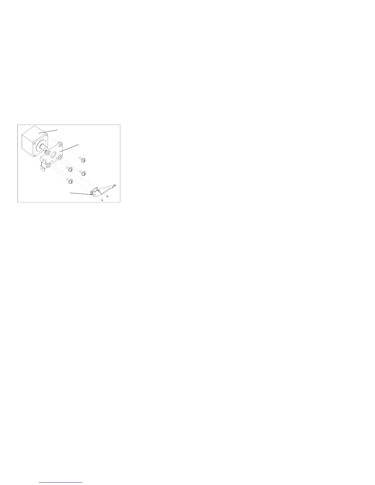
Carriage Motor
Carriage Motor
Bracket/Screws
Print Head Cable
Bracket/Screws
Figure 154. Carriage Motor Bracket Screws.
(Viewed From Front)
Chapter 5. Removals and Adjustments 420