Sensor Cable Assembly
Removal
1. Remove the printer covers. See “Printer Covers” on page 347.
2. Remove the ribbon drive motor and left ribbon cartridge support. See “Ribbon Drive Motor” on page 403.
3. Remove the upper feed roller assembly. See “Upper Feed Roller Shaft Assembly” on page 426.
4. Remove the platen assembly (some steps are completed). See “Platen Assembly” on page 429.
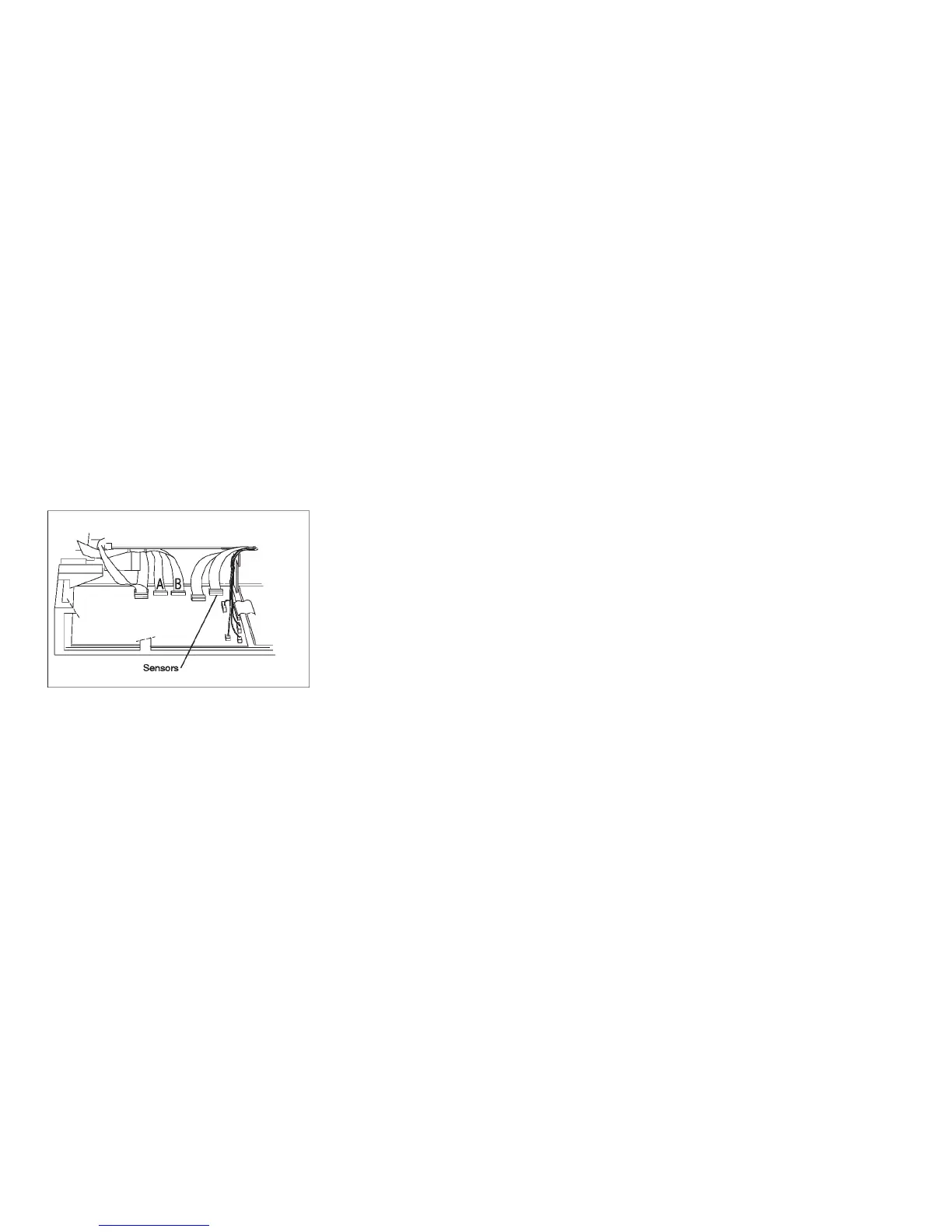
5. Disconnect the sensor cable connector from the logic board. Note the location and path of the cable to aid
installation.
Figure 176. Sensor Cable Connector - Model A00 Early-Level
Chapter 5. Removals and Adjustments 441