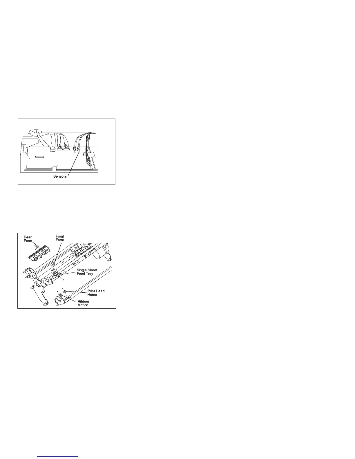
6. Remove the screws for each of the 5 sensors and remove the cable assembly.
Figure 177. Sensor Cable Connector - Model A00 Late-Level and Models 001, 002, and 003.
Models 001 and 003
have connectors A and B. Model 002 has only connector B.
Figure 178. Sensor Cable and Sensor Locations
Chapter 5. Removals and Adjustments 442