Table 11. MAP 0150: Power Supply (continued)
Questions/Actions Yes No
3.
Put the covers in the service position. See
“Removing Covers” on page 275. Disconnect the
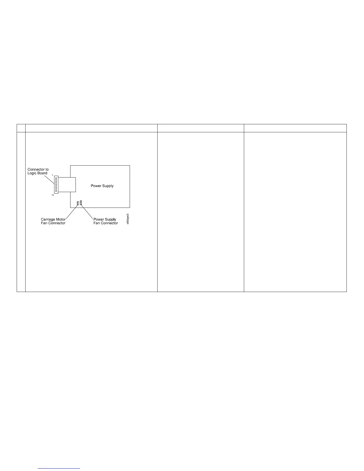
power supply fan from the power supply board.
Power Supply Pins and Connectors:
Disconnect the carriage motor fan from the power
supply board. Disconnect the power supply cable to
the logic board. Plug the power cord to the printer,
then to the power source. Power on (|) the printer.
Measure the power supply connector voltages.
Measure between a connector ground pin and the
voltage pins. See “Reference Table 8, Power
Supply Connector Pins and Voltages” on page 156
for pins and voltages. Are the voltage
measurements OK?
Go to step 4 on page 78. Install a new power supply. See “Power
Supply” on page 400.
Run T&D in automatic mode to verify
correct printer operation. For Model
A00, see “How To Run the Test and
Diagnostic (T&D) Programs” on
page 161. For Models 001, 002, or 003,
see “How To Run the Test and
Diagnostic (T&D) Programs” on
page 201.
Chapter 1. Diagnosing Problems
77