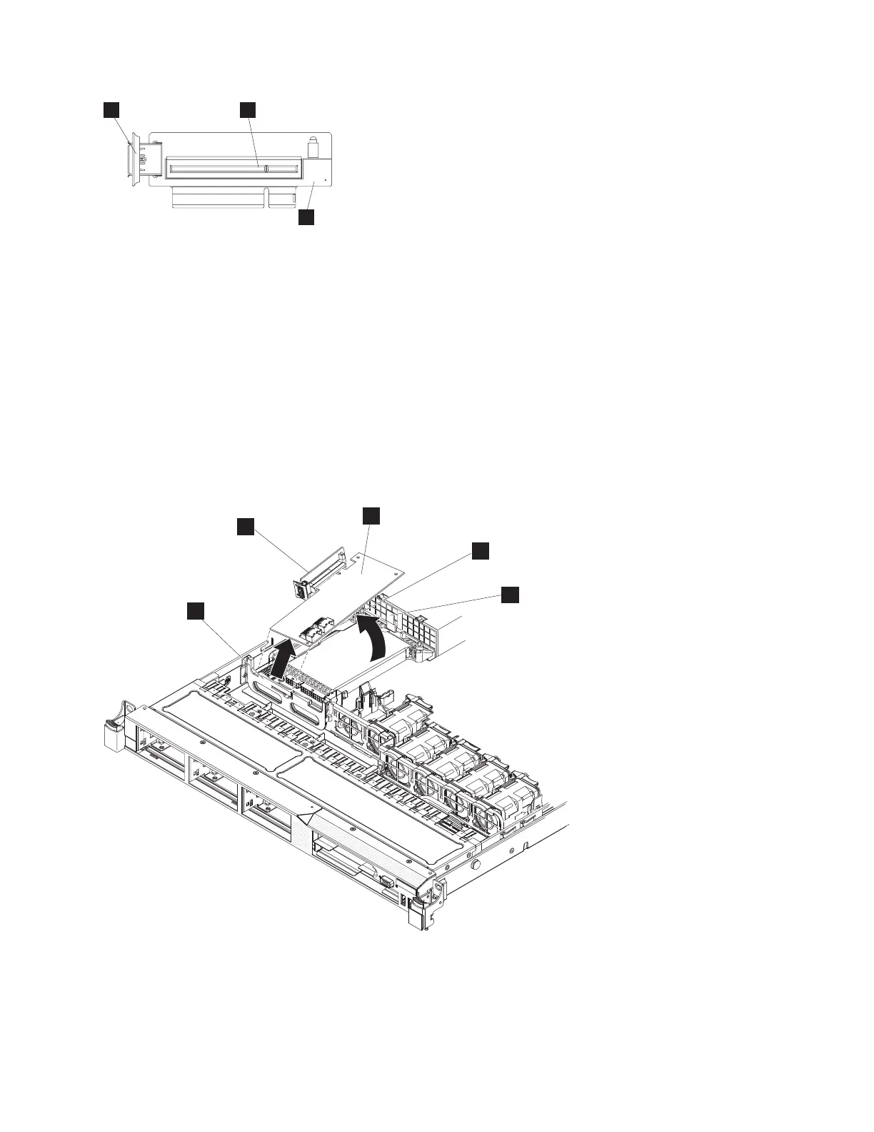
1 USB connector
2 Disk-controller connector
3 USB riser-card assembly (shown without the disk controller)
8. Remove the SAS cable that runs to the boot-drive-bay connector on the left side of the back of the
disk backplane, when viewed from the rear, from the connector on the disk-controller and USB
riser-card assembly that is closer to the power supply.
9. If present, remove the SAS cable that runs to disk-drive-bay connector in the center of the back of
the disk backplane, when viewed from the rear, from the connector on the disk-controller and USB
riser-card assembly that is closer to the front of the node.
10. Grasp the disk controller near the end next to the power-supply cage while you press the black
plastic tab (next to the power supply) toward the power supply.
1 Disk-controller front-retention bracket
2 Disk-controller and USB riser-card assembly
3 Disk controller
4 Alignment post
3
1
2
Figure 204. USB riser-card assembly (SAN Volume Controller 2145-CF8 shown)
5
3
4
1
2
Figure 205. Disengaging the disk-controller front-retention bracket and removing the riser assembly and disk controller
Chapter 2. Removing and replacing parts 209