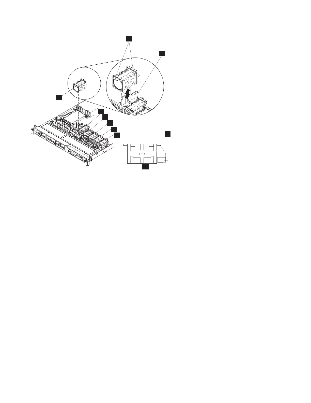
1 Fan 1
2 Fan 2
3 Fan 3
4 Fan 4
5 Fan 5
6 Fan 6
7 Fan tabs
8 Fan connector on the system board
9 Fan connector
10 Side view of fan showing air-flow indicator
The node has six fan positions that are numbered right to left. The LED near the connector of the
failing fan assembly is lit, unless you remove the power cable.
4. Grasp the orange fan tabs on both ends of the existing fan and pull it up out of the node. If you are
removing fans 3 or 4, lift up the clear tab on the DIMM air baffle first.
Figure 239 on page 241 shows a fan being removed from the node.
7
5
6
8
9
10
1
2
3
4
Figure 238. SAN Volume Controller 2145-CG8 or 2145-CF8 fan locations and connectors
240 IBM SAN Volume Controller Hardware Maintenance Guide
|
|
|
|
|
|
|
|
|
|
|
|
|
|
|
|
|
|
|
|

 Loading...


