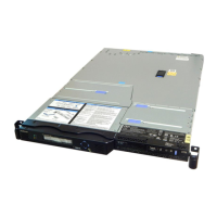
6. Disconnect the light-panel cable
1
and the USB cable
2
from the operator-information panel
board shown in Figure 233.
7. The operator-information panel cable consists of two thick cables and a number of thinner cables
that are bundled together and routed through the chassis. It provides connectivity for the
operator-information panel and the front USB ports. Trace this cable assembly through to the right
side of the system board (next to the power supply) and disconnect the Front USB connector
1
and
the operator-information panel connector
2
from the system board shown in Figure 234.
Figure 233. SAN Volume Controller 2145-8A4 operator-information panel
Figure 234. Connectors for the operator-information panel on the SAN Volume Controller 2145-8A4 system board
Chapter 2. Removing and replacing parts 235

 Loading...


