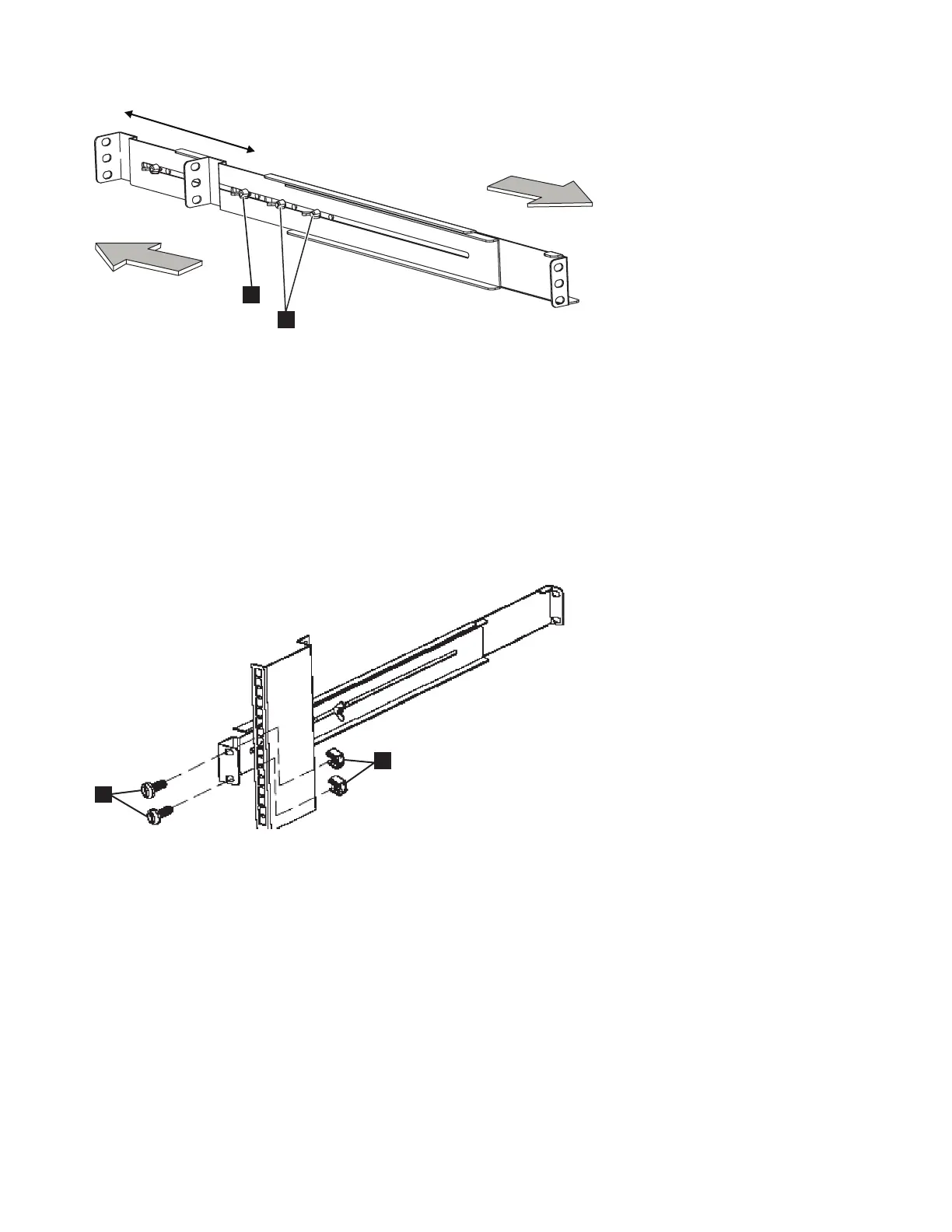
1 Assembly wing nuts
2 Wing nut
5. Select the holes in the rail where you want to position the 2145 UPS-1U.
Note: The bottom flange of the support rail must align with the EIA mark on the rack.
6. Using two M6 × 10 screws (1 in Figure 327) and two clip nuts 2, attach the rail to the rear of the
rack. The customer's rack might be different than the one shown here, and if so, might require
different clip nuts or fasteners.
7. Install two clip nuts (2 and 3 in Figure 328 on page 317) to the front of the rack, then attach the
rail using just one M6 x 10 screw in the bottom mounting hole 1.
Front
Rear
svc00033
2
1
Figure 326. Adjusting the rail depth on the 2145 UPS-1U
1
2
svc00034
Figure 327. Securing the rear rail on the 2145 UPS-1U
316 IBM SAN Volume Controller Hardware Maintenance Guide

 Loading...


