3. Remove the cable-retention bracket and disconnect the power cable from the node. See “Removing
the cable-retention bracket” on page 34.
4. Remove the node from the rack and place it on a flat, static-protective surface. See “Removing the
SAN Volume Controller from a rack” on page 46.
5. Remove the top cover. See “Removing the top cover” on page 77.
6. Remove the SATA backplane far enough to disconnect the two power cables from it. See “Removing
the disk-drive backplane” on page 126.
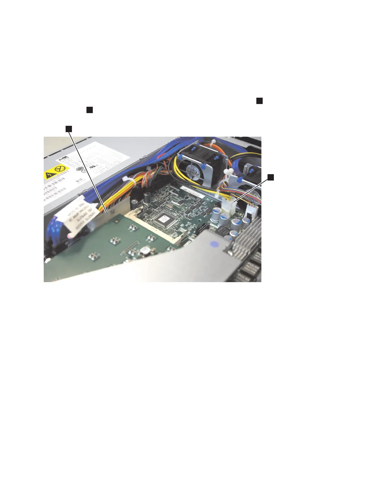
7. Disconnect the power-supply cables from the 24 PIN POWER connector
1
and the POWER
connector
2
on the system board, as shown in Figure 149.
8. Disconnect the power cable, connector P5, which is shown in Figure 150 on page 160, from the
CD/DVD interface card.
svc00484
1
2
Figure 149. SATA connectors on the SAN Volume Controller 2145-8A4 system board
Chapter 2. Removing and replacing parts 159
 Loading...


