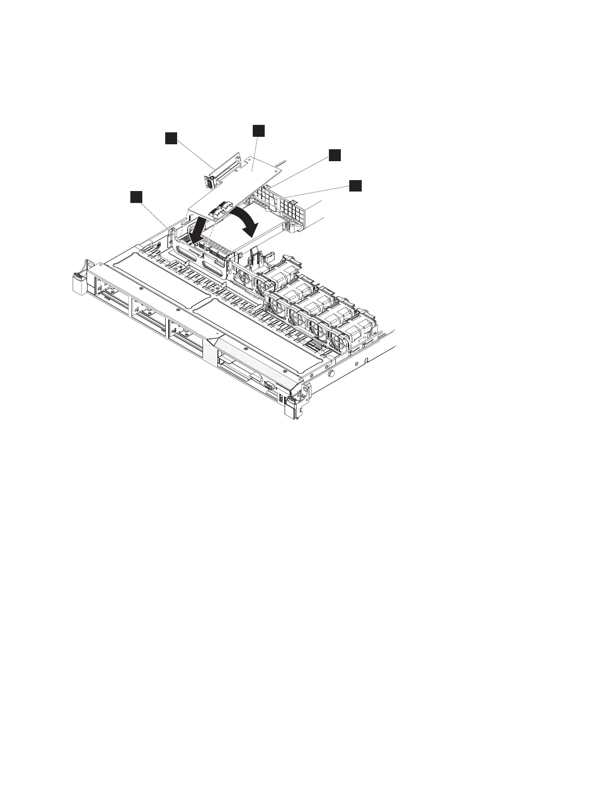
7. Install the disk-controller and USB riser-card assembly.
a. Tilt the USB riser-card assembly slightly and insert the end of the disk controller in the slot on
the retention bracket as shown in the following illustration.
Although the SAN Volume Controller 2145-CF8 is shown in the illustration, the SAN Volume
Controller 2145-CG8 also includes the following parts:
1 Disk-controller front-retention bracket
2 Disk-controller and USB riser-card assembly
3 Disk controller
4 Alignment post
5 Plastic tab
b. Align the riser-card assembly keys correctly with the connector on the system board and press
down on the assembly until it is seated firmly into the connector on the system board.
8. Connect the USB service-controller cable to the USB connector on the USB riser-card assembly, if the
cable is not connected, as described in “Removing and replacing the SAN Volume Controller
2145-CG8 or 2145-CF8 service controller cable” on page 88.
5
3
4
1
2
Figure 206. Engaging the disk-controller front-retention bracket and replacing the riser assembly and disk controller
Chapter 2. Removing and replacing parts 211
|
|
|
|
|
|
|

 Loading...


