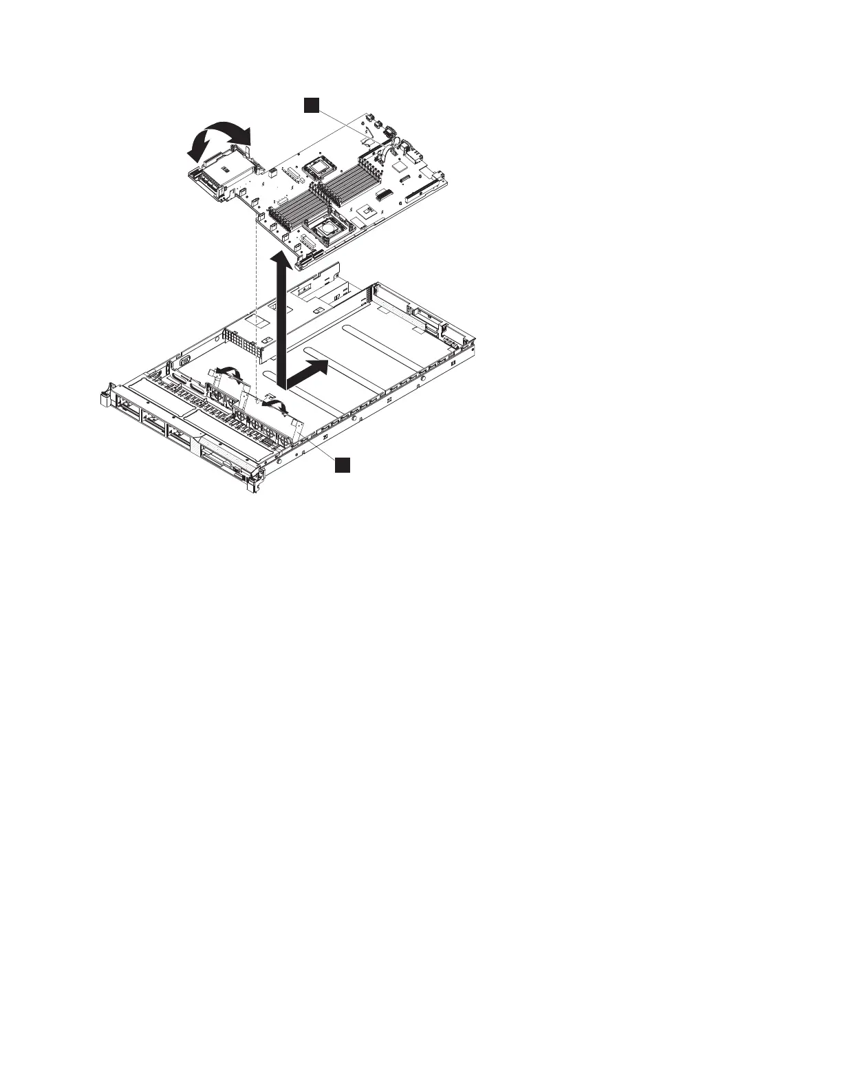
1 System-board handle
2 Fan-assembly bracket
2. Grasp the fan assembly brackets and rotate them down toward the chassis.
3. Replace all of the cables that were removed previously.
4. Reinstall the hot-swap fans, as described in “Replacing the SAN Volume Controller 2145-CG8 or
2145-CF8 fans” on page 245.
5. Reinstall the microprocessor and heat sink, as described in “Replacing the SAN Volume Controller
2145-CG8 or 2145-CF8 microprocessor” on page 259.
6. Reinstall the DIMMs, as described in “Replacing the memory modules (DIMM)” on page 109.
7. Reinstall the white plastic air baffles.
8. Reinstall the power supply units, as described in “Replacing a SAN Volume Controller 2145-CG8 or
2145-CF8 power supply” on page 163.
9. Replace the disk-controller and USB riser-card assembly, as described in “Replacing the SAN Volume
Controller 2145-CG8 or 2145-CF8 disk-controller and USB riser-card assembly” on page 210.
10. Replace the optional high-speed SAS-adapter and riser-card assembly, as described in “Replacing the
SAN Volume Controller 2145-CG8 or 2145-CF8 high-speed SAS adapter assembly” on page 198.
11. Replace the Fibre Channel adapter and riser card. See “Replacing the Fibre Channel adapter
assembly” on page 185.
12. Make sure that all cables, adapters, and other components are installed and seated correctly and that
you have not left loose tools or parts inside the node. Make sure that all internal cables are correctly
routed. If you disconnected the Fibre Channel and Ethernet cables, make sure that each cable is
reconnected to the same port from which it was removed.
13. Replace the top cover. See “Replacing the top cover” on page 81.
14. If you removed the node from the rack, replace the node in the rack, as described in “Replacing the
SAN Volume Controller in a rack” on page 55.
1
2
Figure 290. Removing and replacing the SAN Volume Controller 2145-CG8 or 2145-CF8 system board
Chapter 2. Removing and replacing parts 289
|
|

 Loading...


