7: BASIC INSTRUCTIONS
OPENNET CONTROLLER USER’S MANUAL 7-15
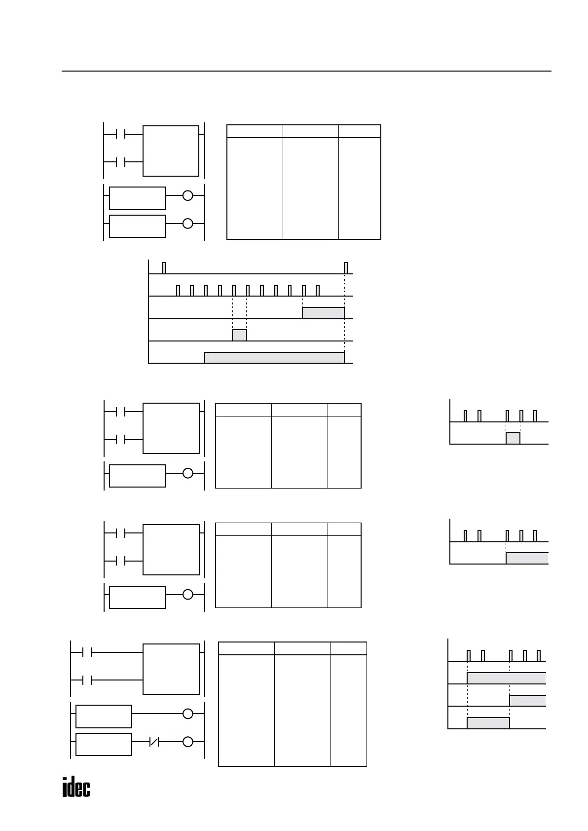
Examples: CC= and CC≥ (Counter Comparison)
Ladder Diagram 1
Timing Chart
CC=
5
C2
Rung 1
CNT
C2
10
I1
Reset
Pulse
I0
CC>=
3
C2
Rung 2
Reset Input I0
ON
OFF
Pulse Input I1
ON
OFF
C2
ON
OFF
Output Q1
ON
OFF
1
Output Q0
• • •
23456
ON
OFF
78910
Prgm Adrs Instruction Data
0
1
2
3
4
5
6
7
8
9
LOD
LOD
CNT
CC=
OUT
CC≥
OUT
I0
I1
C2
10
C2
5
Q0
C2
3
Q1
Program List
Output Q0 is on when counter C2 current
value is 5.
Output Q1 is turned on when counter C2
current value reaches 3 and remains on
until counter C2 is reset.
Q0
Q1
Ladder Diagram 2
Pulse Input I2
ON
OFF
Output Q0
ON
OFF
Timing Chart
1
• • •
500 501 5022
Output Q0 is on when counter C30 current
value is 500.
CC=
500
C30
Rung 1
CNT
C30
1000
I2
Reset
Pulse
I1
Rung 2
Prgm Adrs Instruction Data
0
1
2
3
4
5
6
LOD
LOD
CNT
CC=
OUT
I1
I2
C30
1000
C30
500
Q0
Program List
Q0
Ladder Diagram 3
Pulse Input I4
ON
OFF
Output Q1
ON
OFF
Timing Chart
1
• • •
350 351 3522
Output Q1 is turned on when counter C31
current value reaches 350 and remains on
until counter C31 is reset.
CC>=
350
C31
Rung 1
CNT
C31
500
I4
Reset
Pulse
I3
Rung 2
Prgm Adrs Instruction Data
0
1
2
3
4
5
6
LOD
LOD
CNT
CC>=
OUT
I3
I4
C31
500
C31
350
Q1
Program List
Q1
Ladder Diagram 4
Pulse Input I6
ON
OFF
≥C20 (100)
ON
OFF
Timing Chart
100
• • •
150 151 152101
Q2
Output Q2
ON
OFF
Output Q3
ON
OFF
• • •
Output Q3 is on when counter C20 current
value is between 100 and 149.
Prgm Adrs Instruction Data
0
1
2
3
4
5
6
7
8
9
10
LOD
LOD
CNT
CC>=
OUT
CC>=
ANDN
OUT
I5
I6
C20
500
C20
150
Q2
C20
100
Q2
Q3
Program List
CC>=
150
C20
CNT C20
500
I6
Reset
Pulse
I5
CC>=
100
C20
Q3
Q2
Phone: 800.894.0412 - Fax: 888.723.4773 - Web: www.clrwtr.com - Email: info@clrwtr.com

 Loading...

