7: BASIC INSTRUCTIONS
OPENNET CONTROLLER USER’S MANUAL 7-23
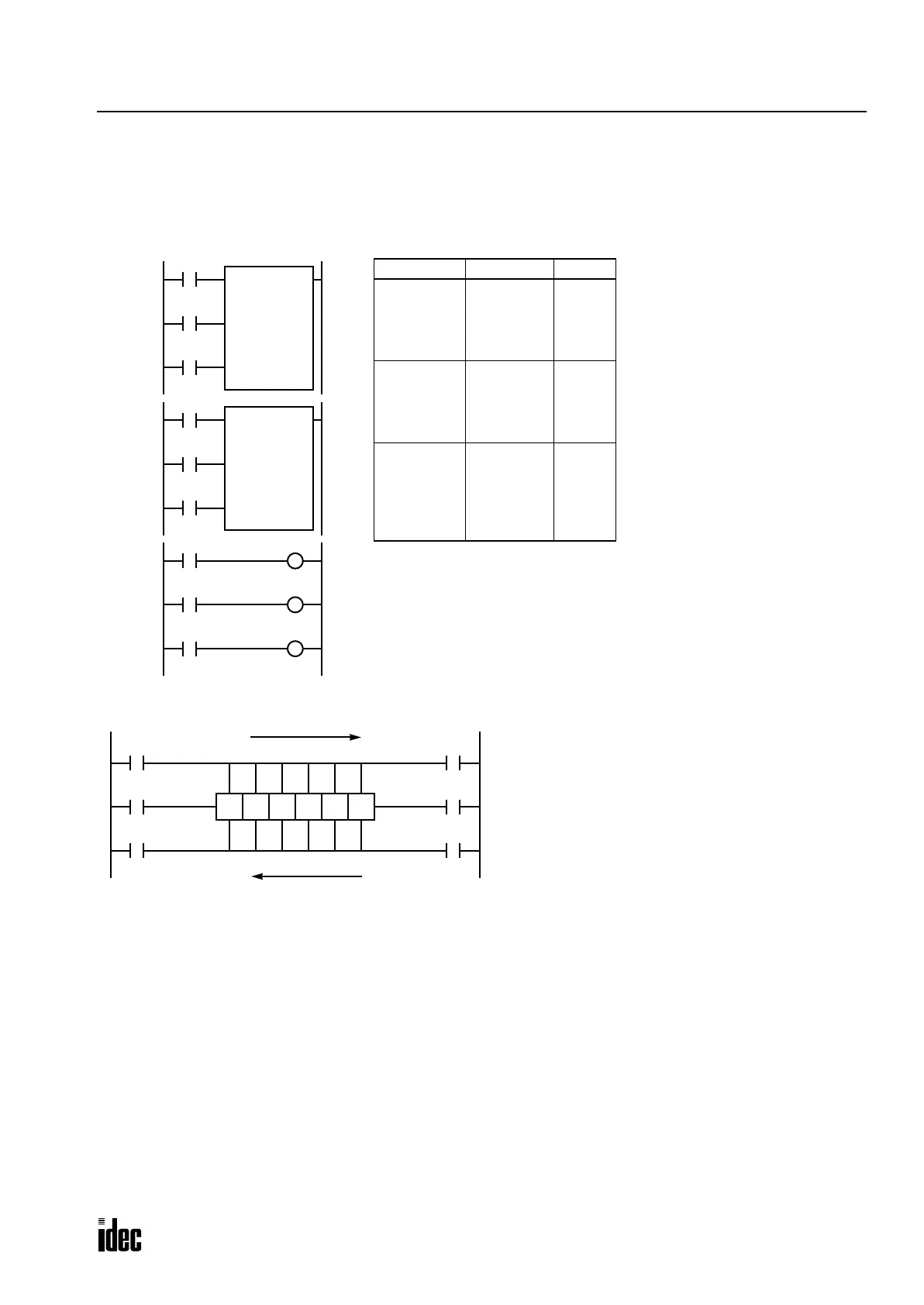
Bidirectional Shift Register
A bidirectional shift register can be created by first programming the SFR instruction as detailed in the Forward Shift Reg-
ister section on page 7-20. Next, the SFRN instruction is programed as detailed in the Reverse Shift Register section on
page 7-22.
Structural Diagram
I3
I1
R22
Reset
Data
I2
Pulse
R23 R24 R25
Forward Shifting
Last Bit: R22 # of Bits: 6
R26 R27
Note: Output is initiated only for those bits highlighted in bold print.
I4
I6
I5
Reset
Data
Pulse
First Bit: R22 # of Bits: 6
Reverse Shifting
Ladder Diagram
I1
I2
SFR R22
6
I3
Reset
Pulse
Data
Rung 1
I4
I5
SFRN R22
6
I6
Reset
Pulse
Data
Rung 2
R23
Rung 3
R24
R26
Prgm Adrs Instruction Data
Rung 1 0
1
2
3
4
LOD
LOD
LOD
SFR
I1
I2
I3
R22
6
Rung 2 5
6
7
8
9
LOD
LOD
LOD
SFRN
I4
I5
I6
R22
6
Rung 3 10
11
12
13
14
15
LOD
OUT
LOD
OUT
LOD
OUT
R23
Q0
R24
Q1
R26
Q2
Program List
Q0
Q1
Q2
Phone: 800.894.0412 - Fax: 888.723.4773 - Web: www.clrwtr.com - Email: info@clrwtr.com

 Loading...

