2: MODULE SPECIFICATIONS
OPENNET CONTROLLER USER’S MANUAL 2-3
(8) Terminal Block
(9) Expansion Connector
For connecting a digital I/O module or functional module.
(10) Remote I/O Master Module Connector
For connecting a remote I/O master module compatible with INTERBUS. This connector is located on the left side of the
CPU module and usually covered with an end plate. When connecting a remote I/O master module, remove the end plate
from the CPU module and attach the remote I/O master module.
(11) End Plate
A pair of end plates are supplied with the CPU module. Remove the end plate from the CPU module before connecting
digital I/O and functional modules, then attach the end plates on both sides of the assembly. For removing the end plates,
see page 3-3.
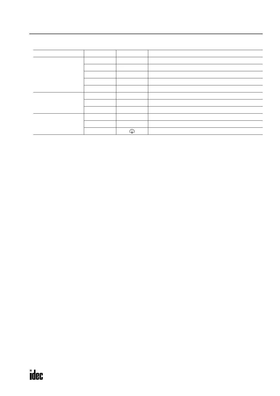
Function Terminal No. Symbol Assignment
High-speed Counter
Terminals
1 COM High-speed counter COM
2A High-speed counter phase A
3B High-speed counter phase B
4Z High-speed counter phase Z
5 HSC OUT High-speed counter comparison output
RS485 Port
6 RS485 A RS485 line A
7 RS485 B RS485 line B
8 RS485 G RS485 line SG
Power Supply Terminals
9 +24V Power supply +24V DC
10 0V Power supply 0V DC
11 Frame ground
Phone: 800.894.0412 - Fax: 888.723.4773 - Web: www.clrwtr.com - Email: info@clrwtr.com

 Loading...

