2: MODULE SPECIFICATIONS
OPENNET CONTROLLER USER’S MANUAL 2-17
16-point Relay Output Module Specifications
Contact Protection Circuit for Relay Output
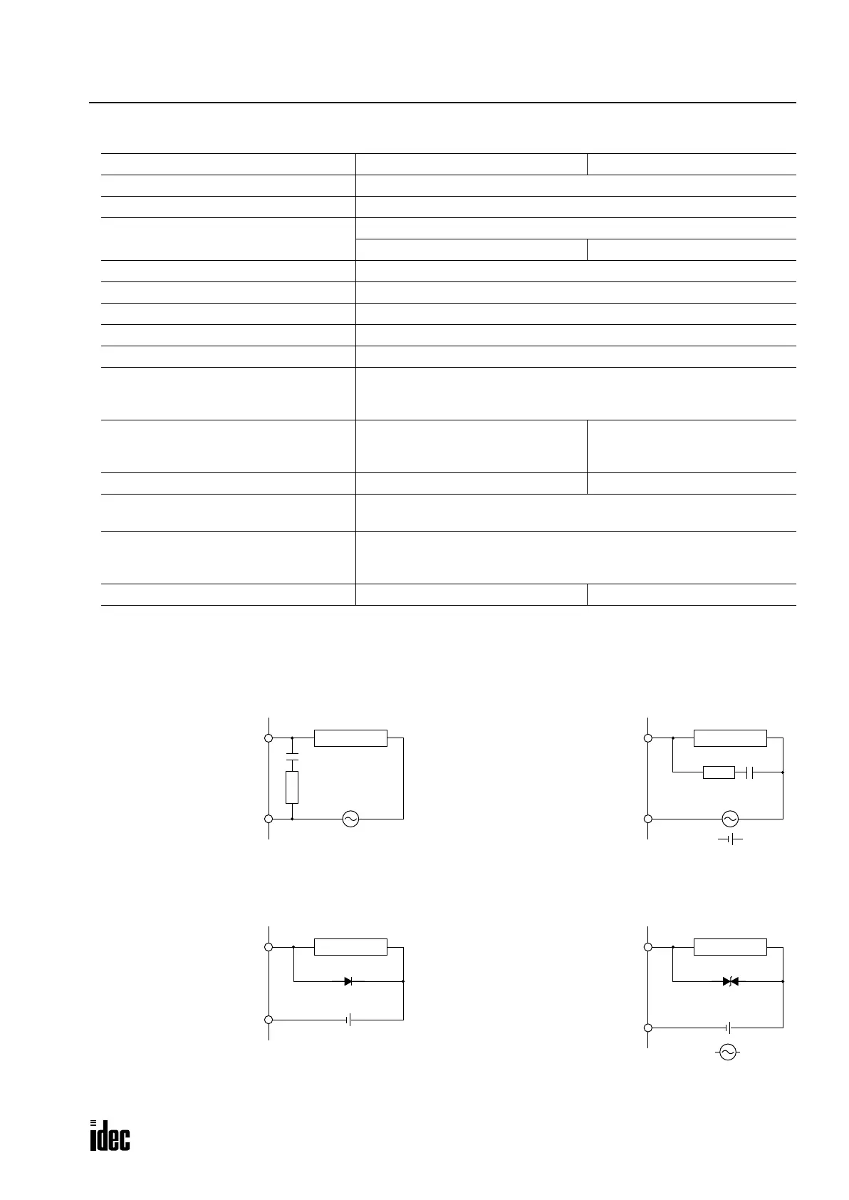
Depending on the load, a protection circuit may be needed for the relay output of the OpenNet Controller. Choose a protec-
tion circuit from A through D shown below according to the power supply and connect the protection circuit to the outside
of the relay output module.
Type No. FC3A-R161 FC3A-R162
Terminal Arrangement See Terminal Arrangement charts on pages 2-22 and 2-23.
Output Points and Common Lines 16 NO contacts in 4 common lines (COM terminals not connected together)
Maximum Load Current
2A per point
8A per common line 7A per common line
Minimum Switching Load 0.1 mA/0.1V DC (reference value)
Initial Contact Resistance 30 mΩ maximum
Electrical Life 100,000 operations minimum (rated load 1,800 operations/hour)
Mechanical Life 20,000,000 operations minimum (no load 18,000 operations/hour)
Rated Load Voltage (resistive/inductive) 240V AC/2A, 30V DC/2A
Dielectric Strength
Between output terminal and FG: 1,500V AC, 1 minute
Between output terminal and internal circuit: 1,500V AC, 1 minute
Between output terminals (COMs): 1,500V AC, 1 minute
Connector on Mother Board
Screw Terminal Block
MSTBA2.5/20-G5.08
(Phoenix Contact)
Nylon Connector
B5PS-VH × 4
(J.S.T. Mfg.)
Connector Insertion/Removal Durability 100 times minimum 50 times minimum
Internal Current Draw
All outputs ON: 170 mA (24V DC)
All outputs OFF: 20 mA (24V DC)
Output Delay
Turn ON time: 6 msec maximum
Chatter: 6 msec maximum
Turn OFF time: 10 msec maximum
Weight (approx.) 260g 230g
Inductive Load
COM
C
R
Output Q
Inductive Load
COM
R
Output Q
C
+
or
–
Inductive Load
COM
Output Q
+–
Inductive Load
COM
Output Q
+
or
–
Varistor
Protection circuit A can be used when the load impedance is
smaller than the RC impedance in an AC load power circuit.
C: 0.1 to 1 µF
R: Resistor of about the same resistance value as the load
Protection circuit B can be used for both AC and DC load
power circuits.
C: 0.1 to 1 µF
R: Resistor of about the same resistance value as the load
Protection circuit D can be used for both AC and DC load
power circuits.
Protection Circuit A Protection Circuit B
Protection Circuit C Protection Circuit D
Protection circuit C can be used for DC load power circuits.
Use a diode with the following ratings.
Reverse withstand voltage: Power voltage of the load circuit × 10
Forward current: More than the load current
Phone: 800.894.0412 - Fax: 888.723.4773 - Web: www.clrwtr.com - Email: info@clrwtr.com

 Loading...

