xii
UHK-430/CCU-430 1710 VER2 (E)
CONTENTS
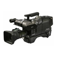
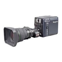
UHK-430/CCU-430
4K/HD
Portable Camera System
OPERATION MANUAL
PRODUCTS CONFORMING TO RoHS DIRECTIVE . . . i
MAINTENANCE OF PRODUCTS CONFORMING TO
RoHS DIRECTIVE..............................ii
INFORMATION TO THE USER ..................iii
SAFETY PRECAUTIONS .......................iv
HOW TO READ THE OPERATION MANUAL .......ix
Chapter 1. OUTLINE
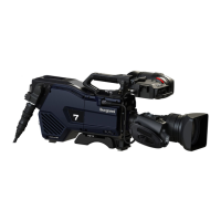
1.1 Overview of UHK-430/CCU-430 .......... 3
1.2 Features of This Product ................ 4
System Versatility ...................... 4
Superb Operation and Ease of Use ........ 5
Employment of New Technology .......... 5
Other Features ........................ 5
1.3 Operating Systems ..................... 6
1.4 Connection Diagram ................... 9
Chapter 2. NAME and FUNCTION
2.1 Camera and Viewfinder ................ 13
Name and Function of the
Name and Function of the
Camera Left Side ..................... 16
Name and Function of the
Camera Front Side .................... 18
Name and Function of the
Camera Rear Side .................... 19
Name and Function of the Viewfinder ..... 22
2.2 Displays in the Viewfinder (VFL201D) ..... 24
LED Indicator ........................ 24
Center Marker, Safety Marker,
Frame Marker ........................ 24
ZEBRA Indicator ..................... 24
Side Mask Function ................... 25
Display Mode ........................ 25
Viewfinder Display .................... 25
2.3 CCU-430 ........................... 28
CCU-430 Name and Function of the
front display (with cover fitted) ........... 28
Names and Functions of CCU-430 Front
Inside Part (Cover Removed). . . . . . . . . . . . 31
Names and Functions of CCU-430 (Back)
.. 32
Chapter 3.
INSTALLATION and CONNECTION
3.1 Preparation .......................... 37
Product Use ......................... 37
Make sure the Power Switch is OFF ...... 37
3.2 Connecting the Power Cable and
Camera Cable ....................... 38
Connecting the AC Power Cable
to the CCU .......................... 38
Connecting the Optical fiber Cable
to the CCU .......................... 38
3.3 Camera and Peripheral Installation and
Connection .......................... 39
Mounting/Removing the Camera
on/from the Tripod .................... 39
Mounting and Removing the Lens ........ 42
Mounting and Removing the Viewfinder . . . 44
Adjust the eypiece position of viewfinder . . 46
Attaching a Microphone ................ 47
Connecting Headsets .................. 48
Attaching a Shoulder Belt .............. 50
Connecting a Monitor to the Camera ...... 51
3.4 Connecting the CCU and Camera ........ 52
Connecting the Camera Cable
(Fiber Cable) ........................ 52
Removing the Fiber Cable .............. 53
3.5 System Setup Diagram ................ 54
3.6 About the GENLOCK System ........... 56
Chapter 4. OPERATION
4.1 Operating Procedures ................. 59
Initial Operation Check ................. 59
Preparation Before Shooting ............ 59
Shooting Settings and Adjustment ........ 59
4.2 Switch Position Check ................. 60
Camera right view .................... 60
Camera rear view ..................... 60
CCU front view ....................... 60
4.3 Turning ON Power .................... 61
To operate the power supply from CCU .... 61
Activating the FIBER SINGLE MODE ..... 63
4.4 Output Signal Check .................. 65
Test Pulse (CAL Signal) Check .......... 65
Color-Bar Signal Check ................ 66
External Chart Check .................. 66