32
UHK-430/CCU-430 1710 VER2 (E)
2.3 CCU-430
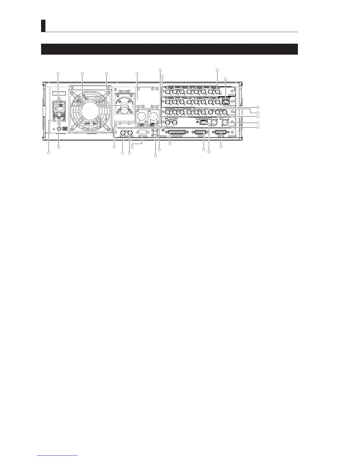
Names and Functions of CCU-430 (Back)
■
Names of CCU-430 (Back)
* * *
HD QTV IN
HD RETURN IN
SDI-OUTPUT-2
MON OUTPUT
HD TRK OUT
VP_OUT
AES OUT
SDI-OUTPUT-1
SYNC OUT
DATA TRK-1
TALLY OUT
COMMUNICATION
I/F
REMOTE
SYS_IF
REFERENCE
RET_MON
GbE TRK
LAN
OCP
CSU
MPU
1
2
1
2
4
1
2
1
1
2
2
3
4
4
3
CAMERA
HD_OUT
SDI-OUTPUT-4
SDI-OUTPUT-3
1
2
3
4
3
2
1
4
AC inlet
Ground terminal
Camera Connector
AES OUT connector
SDI OUT-1, 2
Main line output connector
SYNC OUT
connector
DATA TRU NK
connector
TALLY OUT connector
Gigabit ETHERNET TRUNK connector
HD RETURN IN
Return video input connector
HD QTV video input connecto
HD TRUNK OUT connector
MONI OUT connector
SDI OUT-3, 4
HD video output connector (option)
(
The output configuration may be changed due to the change in specifications.)
Main power
switch
Option area
AUDIO OUT 1, 2
REFERENCE
connector
LAN connector
OCP connector
REMOTE connector
Fan motor
I/F connector
COMMUNICATION
connector
CSU connector
1 5 6
15
12
14
16
17
18
22
21
23
20
24
25
19
107
4
3
11
98
13
2
Caution:
The connectors on the back include optional contents. The module to be inserted may be different (could be not inserted) depending on
\RXUVSHFL¿FDWLRQV,QWKLVGRFXPHQWWKHPRGXOHRXWSXWVORWWKDWRXWSXWV+'YLGHRLQVLPXOWDQHRXVRSHUDWLRQVLVLQVHUWHG
■
Function of CCU-430 (Back)
(1) Fan motor
Fan motor to cool inside of the CCU.
(2) Main power switch
Main switch for CCU power supplies.
(3) AC inlet
$&LQOHWXVHGWRLQSXW$&WR9$&DQGWR9$&FRPPHUFLDOSRZHUVXSSO\WR&&8
(4) Ground terminal
$IUDPHJURXQGWHUPLQDOIRU&&8
It is connected to the housing rack frame of the CCU-430.
(5) Camera Connector
&RQQHFWVWKH&&8DQGWKHFDPHUDZLWKDK\EULGRSWLFDO¿EHUFDPHUDFDEOH
It supplies power to the camera, in addition, it sends and receives various data including main line video signals and communication
commands, etc.
(6) Option area
$SDQHOIRUVSHFLDOVSHFL¿FDWLRQ
(7) Audio OUT (Analog) connector 1, 2
2XWSXWVWKHDXGLRVLJQDOVWKDWKDYHEHHQLQSXWWRWKH0,&$8',2,1FRQQHFWRUVRIWKHFDPHUD
(8) AES OUT Digital audio output connector
2XWSXWVWKHDXGLRVLJQDOVWKDWKDYHEHHQLQSXWWRWKH0,&$8',2,1FRQQHFWRUVRIWKHFDPHUD7KHVLJQDOVDUHFRPSOLDQW
ZLWK$(6(%8IRUPDW
(9) SYNC OUT (Synchronization signal output)connector
2XWSXWVWKHVLJQDOVIRUH[WHUQDOGHYLFHV\QFKURQL]DWLRQ7ULOHYHOV\QF
(10) Data trunk connector
This is a connector for RS-422 signal transmission between camera and CCU. (Channel #1)
(11) TALLY output connector
2XWSXWWKH7$//<287VLJQDOVWKDWDUHXVHGIRUPRQLWRUVHWF