INSTALLATION and CONNECTION
3
53
UHK-430/CCU-430 1710 VER2 (E)
3.4 Connecting the CCU and Camera Head
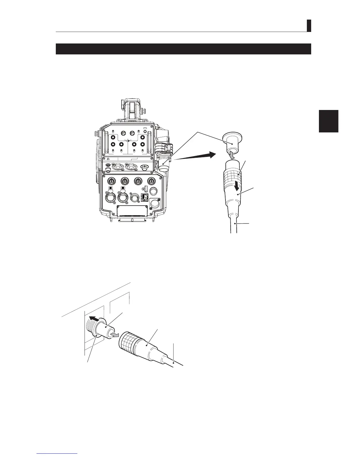
Removing the Fiber Cable
7KLVVHFWLRQH[SODLQVKRZWRUHPRYHWKHFDPHUDFDEOH¿EHUFDEOH
Caution:
:KHQ\RXUHPRYHWKHFDEOHEHVXUHWRKROGWKHSOXJDQGSXOO)DLOXUHWRGRVRPD\GDPDJHWKH¿EHULQWKHFDEOH
■
Camera
LIGHT
RET 1 RET 2 TALLY
CALL
ON
OFF
DIM
1
2
3
4
4
3
2
1
DIM
OFF
ON
ON
OFF
PTT
PROD
BOTH
ENG
ENG
BOTH
PROD
PTT
OFF
ON
INCOM 1
FRONT
REAR
INCOM SEL
FRONT
INCOM 2
INCOM
PGM 1 PGM 2 PGM 2PGM 1
INCOM
INTERCOM 1 INTERCOM 2
DC OUT
GL IN/SYNC OUT
MIC 2MIC 1
GbE TRK
11~17V
DC-IN
TRACKER
+12V
OFF
SDI OUT 1
+48V
+12V
OFF
+48V
SDI OUT 2
USB
REMOTE
SDI OUT 3
SDI I/O 4
12V 1A
Camera rear view
CAMERA connector
(socket )
Unlock ring
Plug
Fiber cable
1 Remove the cable from the camera while pulling the unlocking ring on the fiber cable plug (female) toward you.
,IWKHFRQQHFWRULVORFNHGWKH¿EHUFDEOHFDQQRWEHUHPRYHG,ILWLVORFNHGSXVKWKH¿EHUFDEOHWRZDUGWKH&$0(5$
connector, and then remove as described above.
■
CCU
CAMERA connector
(plug)
nl
k rin
Socket
Fiber cable
2 Remove the cable from the CCU-430 while pushing the unlocking ring of the CAMERA connector on the rear of
CCU-430.
,IWKHFRQQHFWRULVORFNHGWKH¿EHUFDEOHFDQQRWEHUHPRYHG,ILWLVORFNHGSXVKWKH¿EHUFDEOHWRZDUGWKH&$0(5$
connector, and then remove as described above.