52
UHK-430/CCU-430 1710 VER2 (E)
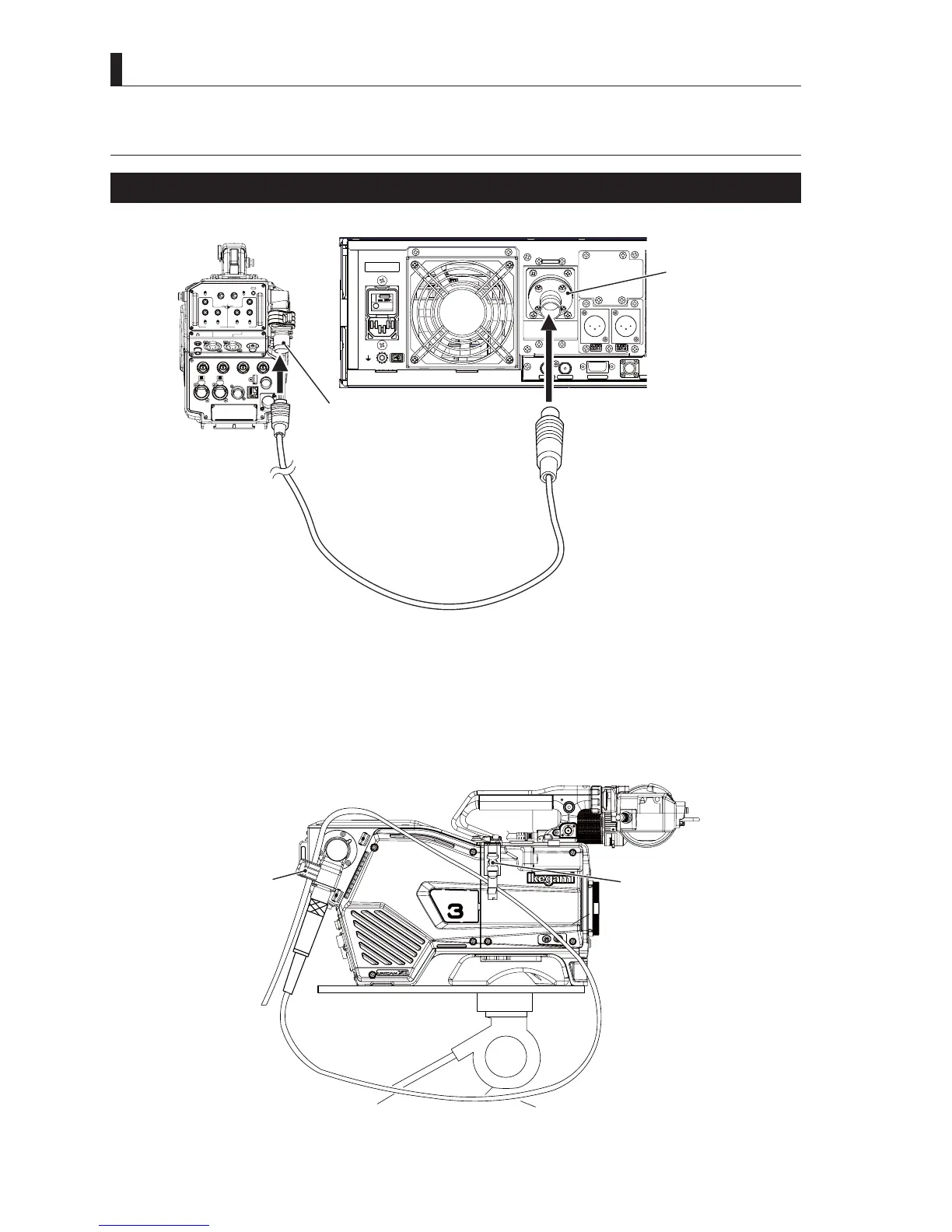
3.4 Connecting the CCU and Camera Head
3.4 Connecting the CCU and Camera
Connecting the Camera Cable (Fiber Cable)
* * *
AES OUT SYNC OUT
DATA TRK-1
TAL L
CAMERA
LIGHT
RET 1 RET 2 TALLY
CALL
ON
OFF
DIM
1
2
3
4
4
3
2
1
DIM
OFF
ON
ON
OFF
PTT
PROD
BOTH
ENG
ENG
BOTH
PROD
PTT
OFF
ON
INCOM 1
FRONT
REAR
INCOM SEL
FRONT
INCOM 2
INCOM
PGM 1
PGM 2 PGM 2PGM 1
INCOM
INTERCOM 1 INTERCOM 2
DC OUT
GL IN/SYNC OUT
MIC 2MIC 1
GbE TRK
11~17V
DC-IN
TRACKER
+12V
OFF
SDI OUT 1
+48V
+12V
OFF
+48V
SDI OUT 2
USB
REMOTE
SDI OUT 3
SDI I/O 4
12V 1A
Fiber cable
Camera connector
Camera connector
Camera rear view
CCU rear view
1
Connect the CAMERA connector on the back of the CCU and the CAMERA connector on the back of the camera
with a fiber cable (hybrid fiber camera cable).
Caution:
- The camera cable has a male plug connector on one end and a female socket connector on the other end. Be sure to connect
the female plug connector to the camera and the female socket connector to the CCU.
6HFXUHWKH¿EHUFDEOHK\EULG¿EHUFDPHUDFDEOHZLWKWKH&$0(5$&$%/(FODPSRQWKHFDPHUDWRUHGXFHVWUHVV6HH
³6$)(7<35(&$87,216´GHVFULEHGDWWKHEHJLQQLQJRIWKLVPDQXDOIRUKRZWRVHFXUHWKHFDEOHZLWKWKHFDEOHFODPSDQG
KRZWRKDQGOHWKH¿EHUFDEOH
RET-1
RET-2
/MIC
Cable clamp
(option)
Cable clamp
Fiber cable