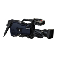
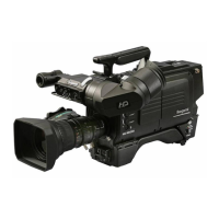
2.1 Camera and Viewfinder
14
UHK-430/CCU-430 1710 VER2 (E)
■
Function of the camera right side
(1) View Finder (VF)
'LVSOD\VYLGHRVIURPWKHFDPHUDUHWXUQYLGHRVDQGYDULRXVFKDUDFWHUVDQGPDUNHUVRQWKHYLHZ¿QGHUVFUHHQLQFKSRUWDEOHFRORU
YLHZ¿QGHULQFKVWXGLRFRORUYLHZ¿QGHUDQGLQFK2/('VWXGLRFRORUYLHZ¿QGHUDUHDYDLODEOH
(2) Camera handle
Hold this handle to carry the camera.
(3) RET-2/MIC button
$VVLJQWKH5(70,&EXWWRQWRHLWKHURIWKHVHIXQFWLRQVVRWKDW\RXFDQWXUQWKHIXQFWLRQRQRIIZLWK\RXUKDQGRQWKHKDQGOH
●
When set to RET-2
RET-2 video is displayed in the viewfinder only while this button is pressed. When this button is not pressed, the
video from the camera is displayed.
●
When set to MIC
This button is used to turn on the intercom microphone of the headset plugged into the camera. While this button is
pressed, the microphone input is turned on.
Reference:
The assignment of functions is set on the menu screen. Please refer to
"Chapter 5 : CAMERA SETTINGS and ADJUSTMENT"
"5.3 Menu Configuration and content" (P. 86)
for setting methods.
(4) RET-1 button
5(7YLGHRLVGLVSOD\HGLQWKHYLHZ¿QGHURQO\ZKLOHWKLVEXWWRQLVSUHVVHG:KHQWKLVEXWWRQLVQRWSUHVVHGWKHYLGHRIURPWKH
camera is displayed.
(5) Shoulder Belt Hooks
Hooks to be used to attach a shoulder belt (option).
Reference:
Please refer to
"Chapter 3 : INSTALLATION AND CONNECTION" "3.3 Camera and Peripheral Installation and
Connection" "Attaching a Shoulder Belt" (P. 50)
for more information.
(6) POWER Indicator
Displays the status of power to the camera
*UHHQOLJKW 3RZHULVVXSSOLHG
5HGOLJKW 6WDQGE\VWDWXV
(7) POWER Switch
This switch is used to turn on/off the camera and select power sources.
&&8 3RZHULVVXSSOLHGIURPWKH&&8YLDWKHFDPHUD
2)) 3RZHULVWXUQHGRII
(;7 3RZHULVVXSSOLHGIURPDQH[WHUQDOSRZHUVRXUFH6HOHFWWKLVWRVXSSO\SRZHUYLDWKH'&,1FRQQHFWRU
Caution:
,I\RXWXUQRQWKHSRZHUDQGWXUQHGLWRQDJDLQZDLWIRUVHFRQGVEHIRUHWXUQLQJRQ
(8) Shoulder Pad
Place this on your shoulder when carrying the camera.
(9) MENU SEL knob/ENTER button
Turn the knob to select the operation you wish to use from the menu items displayed on the VF screen, and press this button to
select. The contents of the menu and setting methods are explained in
"Chapter 5 : CAMERA SETTINGS and ADJUSTMENT"
.
(10) INTERCOM PGM Control knob/Color Filter Selector button
7KLVFRQWUROLVXVHGWRDGMXVWWKH3*0YROXPHRIWKHLQWHUFRPV\VWHPZKHQ(1*RU352'LVVHOHFWHGXVLQJWKH,17(5&20
)521795VHOHFWRUVZLWFKRQWKHEDFNRIWKHFDPHUD3UHVVWKH),/7(5+($'EXWWRQRQWKHULJKWVLGHRIWKHFDPHUDDQGXVHWKH
FRORU¿OWHUWRVZLWFKWKHFRORUWHPSHUDWXUHZKLOHWKHRSHUDWLRQULJKWLVRQWKHFDPHUDVLGH3OHDVHUHIHUWR
"Chapter 5 : CAMERA
SETTINGS and ADJUSTMENT"
"Controlling the ND Filter and Color Filter" (P. 125)
for more information.