64
UHK-430/CCU-430 1710 VER2 (E)
4.3 Turning ON Power
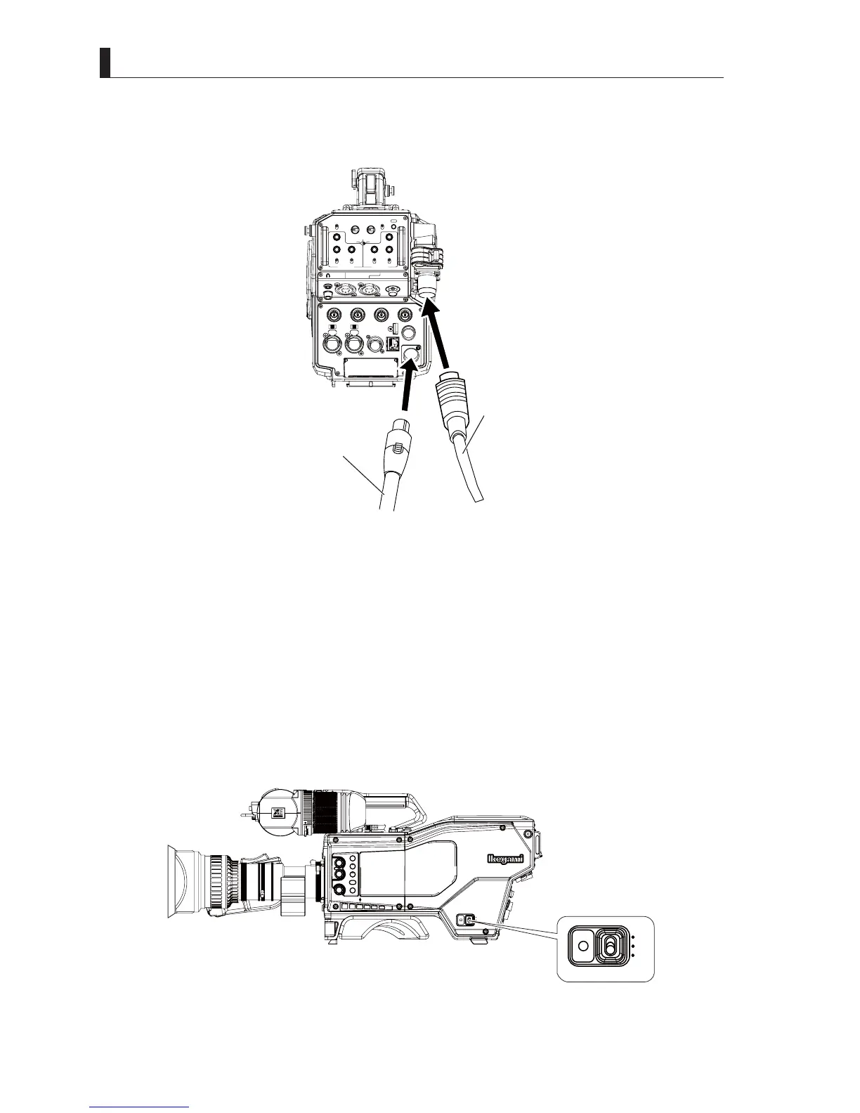
3 Connect the connector from an external power supply to the DC IN connector on the back of the camera.
Connect the camera cable from CCU to the camera connector on the back of the camera.
LIGHT
RET 1 RET 2 TALLY
CALL
ON
OFF
DIM
1
2
3
4
4
3
2
1
DIM
OFF
ON
ON
OFF
PTT
PROD
BOTH
ENGENG
BOTH
PROD
PTT
OFF
ON
INCOM 1
FRONT
REAR
INCOM SEL
FRONT
INCOM 2
INCOM
PGM 1
PGM 2 PGM 2PGM 1
INCOM
INTERCOM 1 INTERCOM 2
DC OUT
GL IN/SYNC OUT
MIC 2MIC 1
GbE TRK
11~17V
DC-IN
TRACKER
+12V
OFF
SDI OUT 1
+48V
+12V
OFF
+48V
SDI OUT 2
USB
REMOTE
SDI OUT 3
SDI I/O 4
12V 1A
Fiber cable
DC Power cable
4 Turn on the CCU power supply.
5 Turn on "FIBER SINGLE MODE" in the CCU Menu setting.
Reference:
Please refer to
"6.1 Basic Operation of Menu Screen" (P. 131)
and
"6.2 CCU Menu Configuration and Contents",
"Setting the SYSTEM SETTING (2/2)", "CONFIGURATION" (P. 143)
IRUWKHVHWWLQJRI),%(56,1*/(02'(
6 Turn on the camera power switch of the CCU side.
7 Turn on the external power switch.
8 Turn the POWER switch on the right side of the camera to the "EXT" postion.
7XUQRQ),%(56,1*/(02'(LQWKH&$0(5$(QJLQHHU0HQXVHWWLQJ
CCU
OFF
EXT
POWER
FILTER
HEAD
F2
F1
MIC
INCOM/ND
PGM/CC
MENU
VF
CHAR
CCU
OFF
EXIT
POWER