5-37
DEVICE CONFIGURATION
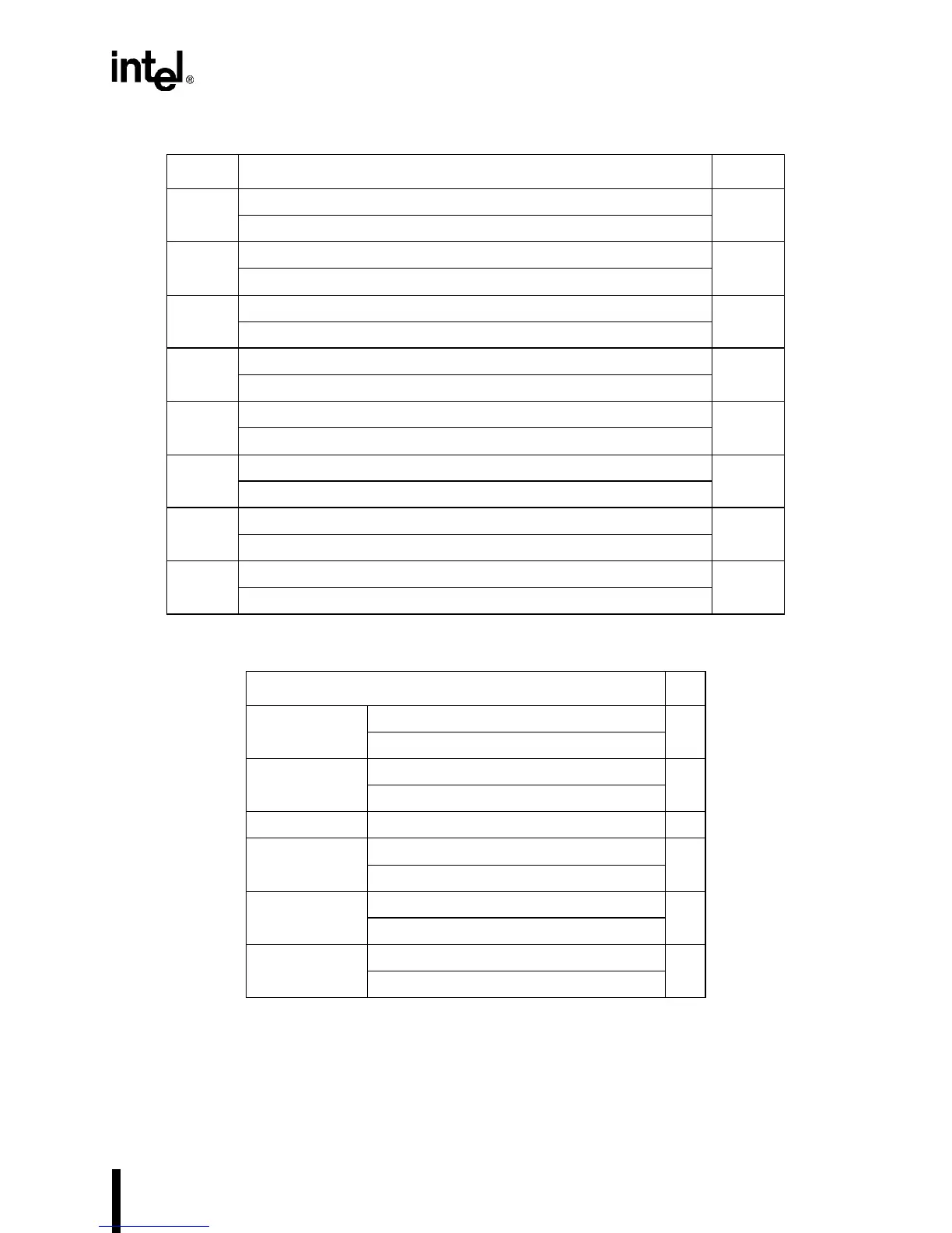
Table 5-12. INTCFG Register Design Worksheet
Table 5-13. SIOCFG Register Design Worksheet
Bit # INTCFG Value
7 0 = CAS2:0 disabled to pins
1 = CAS2:0 enabled from pins
6 0 = SIOINT1 connected to master IR3
1 = P3.1 connected to IR3
5 0 = SIOINT0 connected to master IR4
1 = P3.0 connected to IR4
4 0 = DMAINT connected to slave IR4. INT6 connected to slave IR5.
1 = INT6 connected to slave IR4. DMAINT connected to slave IR5.
3 0 = VSS connected to slave IR6
1 = INT7 connected to slave IR6
20 =V
SS
connected to slave IR5
1 = INT6 connected to slave IR5
1 0 = SSIO Interrupt to slave IR1
1 = INT5 connected to slave IR1
0 0 = VSS connected to slave IR0
1 = INT4 connected to slave IR0
SIOCFG
7 0 = SIO1 modem sigs. conn. to pin muxes
1 = SIO1 modem signals internal
6 0 = SIO0 modem sigs. conn. to pin muxes
1 = SIO0 modem signals internal
5–3 Reserved
2 0 = PSCLK connected to SSIO BLKIN
1 = SERCLK connected to SSIO BCLKIN
1 0 = COMCLK connected to SIO1 BCLKIN
1 = SERCLK connected to SIO1 BCLKIN
0 0 = COMCLK connected to SIO0 BCLKIN
1 = SERCLK connected to SIO0 BCLKIN