Intel386™ EX EMBEDDED MICROPROCESSOR USER’S MANUAL
18-8
18.2.4 Data Registers
The test-logic unit uses three data registers: bypass, identification code, and boundary-scan. The
instruction determines which data register is used.
The single-bit bypass register (BYPASS) provides a minimal-length serial path between TDI and
TDO. During board-level testing, you can use this path for any devices that are not currently un-
der test. This speeds access to the data registers for the devices that are being tested.
The 32-bit identification code register (IDCODE) identifies a device by manufacturer, part num-
ber, and version number. Figure 18-4 describes the register and shows the values for the Intel386
EX processor.
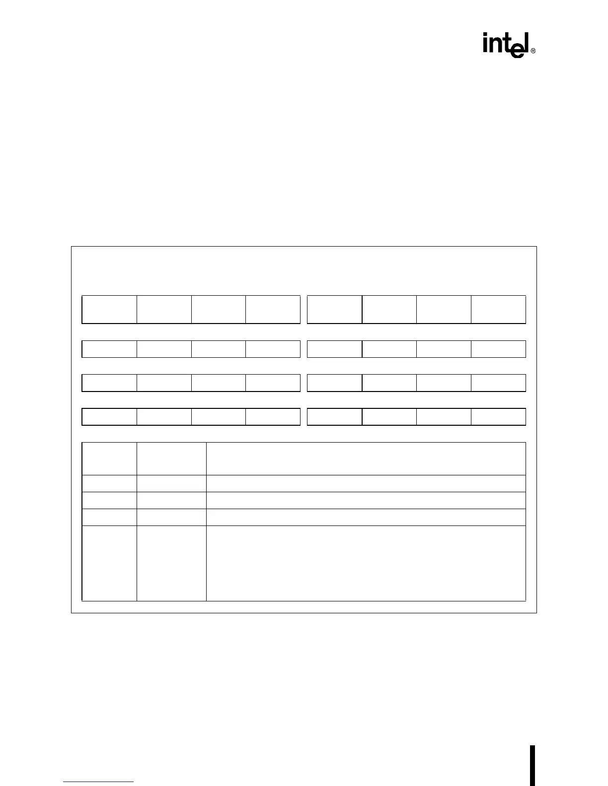
Figure 18-4. Identification Code Register (IDCODE)
Identification Code Register
IDCODE Reset State:
2027 0013H (3V)
2827 0013H (5V)
31 24
00100 (3V)
1 (5V)
000
23 16
0010 0111
15 8
0000 0000
7 0
0001 0011
Bit
Number
Bit
Mnemonic
Function
31–28 V3:0 Device version number.
27–12 PN15:0 Device part number.
11–1 MFR10:0 Manufacturer identification (compressed JEDEC106-A code).
0 IDP Identification Present. Always true for this device.
This is the first data bit shifted out of the device during a data scan
immediately following an exit from the test-logic-reset state. A one
indicates that an IDCODE register is present. (A zero originates from the
BYPASS register and indicates that the device being interrogated has no
IDCODE register.)