Intel386™ EX EMBEDDED PROCESSOR USER’S MANUAL
10-28
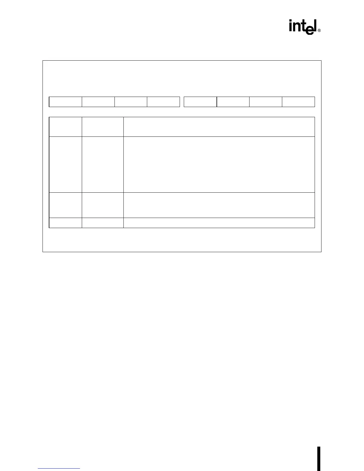
Figure 10-27. Timer Control Register (TMRCON – Counter-latch Format)
When a counter receives a counter-latch command, it latches the count. This count remains
latched until you either read the count or reconfigure the counter. When you send multiple
counter-latch commands without reading the counter, only the first counter-latch command latch-
es the count value.
After issuing a counter-latch command, you can read the counter’s TMRn register. When reading
the counter’s TMRn register you must follow the counter’s programmed read selection (least-sig-
nificant byte only, most-significant byte only, or least-significant byte followed by the most-sig-
nificant byte). If the counter is programmed for two-byte counts, you must read two bytes. You
need not read the two bytes consecutively; you may insert read, write, or programming operations
between the byte reads.
Timer Control (Counter-latch Format)
TMRCON
Expanded Addr:
ISA Addr:
Reset State:
F043H
0043H
XXH
7 0
SC1 SC0 0 0 0 0 0 0
Bit
Number
Bit
Mnemonic
Function
7–6 SC1:0 Select Counter:
These bits specify the counter that receives the counter-latch command.
00 = counter 0
01 = counter 1
10 = counter 2
11 is not an option for TMRCON’s counter-latch format. Selecting 11
accesses TMRCON’s read-back format, which is shown in Figure 10-29.
5–4 — Write zeros to these bits to issue a counter-latch command to the
counter specified by bits 7–6.
01, 10, and 11 are not valid options for TMRCON’s counter-latch format.
3–0 — Reserved; for compatibility with future devices, write zeros to these bits.
NOTE: Bits 5–0 serve another function when you select the read-back command (SC1:0 = 11). See
Figure 10-29 for the read-back bit functions.