11-21
ASYNCHRONOUS SERIAL I/O UNIT
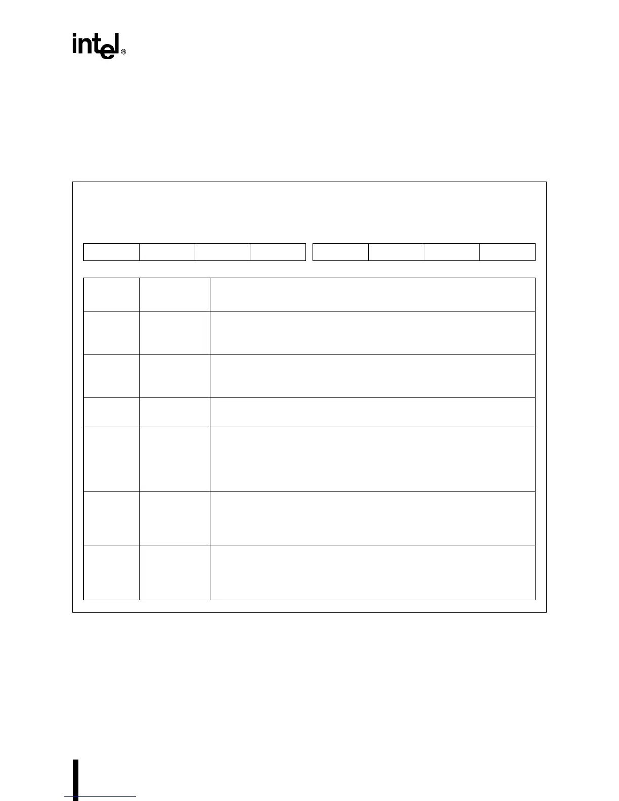
11.3.2 SIO and SSIO Configuration Register (SIOCFG)
Use SIOCFG to select the baud-rate generator clock source for the SIO channels and to have a
channel’s modem input signals connected internally rather than to package pins. Selecting the in-
ternal modem signal connection option connects RTS# to CTS#, DTR# to DSR# and DCD#, and
V
CC
to RI#. The modem signal connections for this internal option are shown in Figure 11-20.
Figure 11-11. SIO and SSIO Configuration Register (SIOCFG)
SIO and SSIO Configuration
SIOCFG
(read/write)
Expanded Addr:
ISA Addr:
Reset State:
F836H
—
00H
7 0
S1M S0M — — — SSBSRC S1BSRC S0BSRC
Bit
Number
Bit
Mnemonic
Function
7 S1M SIO1 Modem Signal Connections:
0 = Connects the SIO1 modem input signals to the package pins.
1 = Connects the SIO1 modem input signals internally.
6 S0M SIO0 Modem Signal Connections:
0 = Connects the SIO0 modem input signals to the package pins.
1 = Connects the SIO0 modem input signals internally.
5–3 — Reserved. These bits are undefined; for compatibility with future devices,
do not modify these bits.
2 SSBSRC SSIO Baud-rate Generator Clock Source:
0 = Connects the internal PSCLK signal to the SSIO baud-rate
generator.
1 = Connects the internal SERCLK signal to the SSIO baud-rate
generator.
1 S1BSRC SIO1 Baud-rate Generator Clock Source:
0 = Connects the COMCLK pin to the SIO1 baud-rate generator.
1 = Connects the internal SERCLK signal to the SIO1 baud-rate
generator.
0 S0BSRC SIO0 Baud-rate Generator Clock Source:
0 = Connects the COMCLK pin to the SIO0 baud-rate generator.
1 = Connects the internal SERCLK signal to the SIO0 baud-rate
generator.