Intel386™ EX EMBEDDED MICROPROCESSOR USER’S MANUAL
16-8
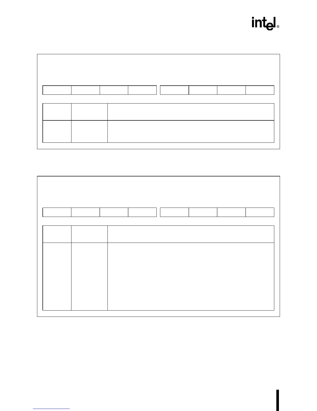
Figure 16-4. Port Direction Register (P
n
DIR)
Figure 16-5. Port Data Latch Register (P
n
LTC)
Port DIrection
P
n
DIR (
n
=1–3)
(read/write)
Expanded Addr:
ISA Addr:
Reset State:
F864H, F86CH, F874H
—
FFH
7 0
PD7 PD6 PD5 PD4 PD3 PD2 PD1 PD0
Bit
Number
Bit
Mnemonic
Function
7–0 PD7:0 Pin Direction:
0 = Configures the pin as a complementary output.
1 = Configures the pin as an open-drain output or high-impedance input.
Port Data Latch
P
n
LTC (
n
=1–3)
(read/write)
Expanded Addr:
ISA Addr:
Reset State:
F862H, F86AH, F872H
—
FFH
7 0
PL7 PL6 PL5 PL4 PL3 PL2 PL1 PL0
Bit
Number
Bit
Mnemonic
Function
7–0 PL7:0 Port Data Latch:
Writing a value to a PL bit causes that value to be driven onto the
corresponding pin.
For a complementary output, write the desired pin value to its PL bit.
This value is strongly driven onto the pin.
For an open-drain output, a one results in a high-impedance (input) state
at the pin.
For a high-impedance input, write a one to the corresponding PL bit. A
one results in a high-impedance state at the pin, allowing external
hardware to drive it.