12-33
DMA CONTROLLER
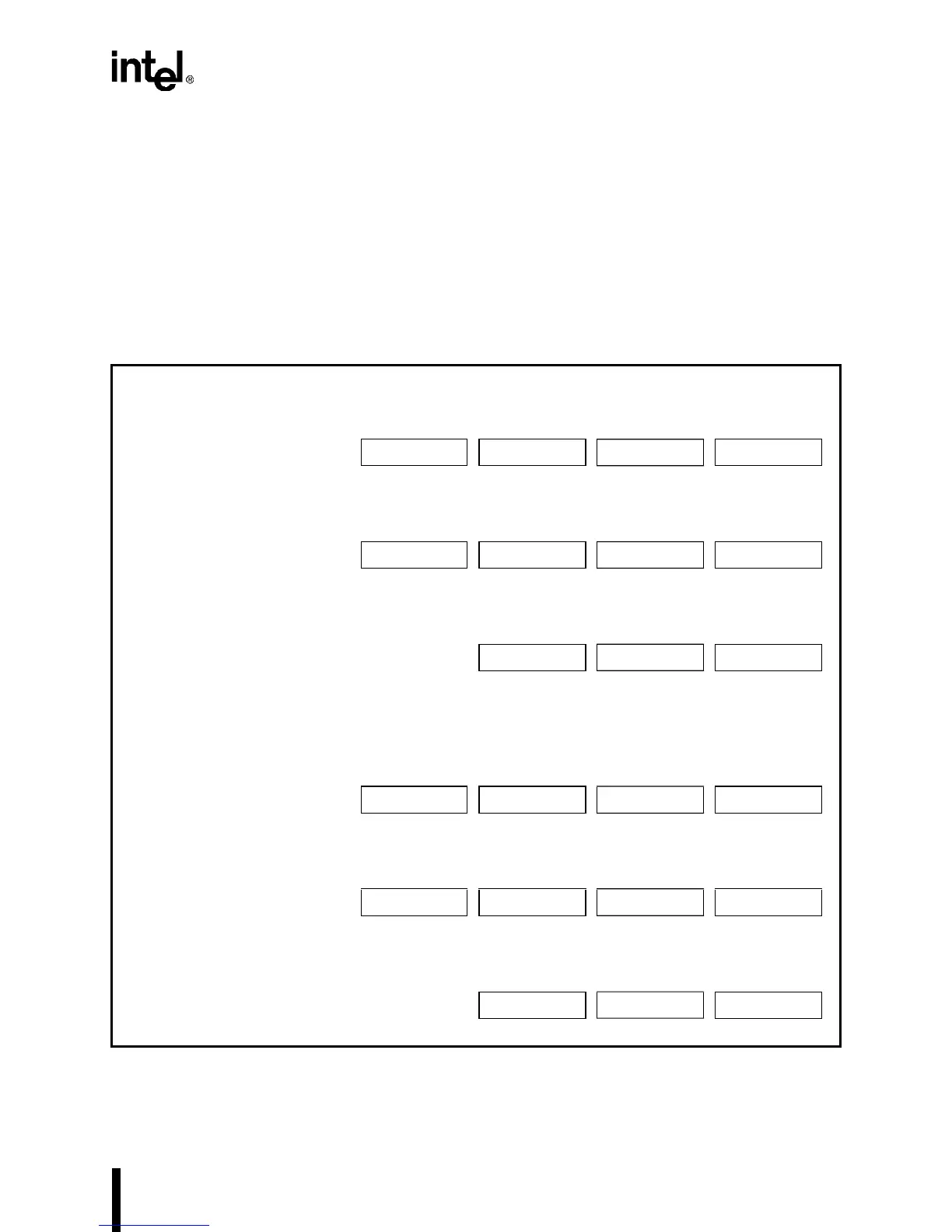
12.3.3 Channel Registers
To program a DMA channel’s requester and target addresses and its byte count, write to the DMA
channel registers. Some of the channel registers require the use of a byte pointer (BP) flip-flop to
control the access to the upper and lower bytes. After you write or read a register that requires a
byte pointer specification, the DMA toggles the byte pointer. For example, writing to
DMA0TAR0 with BP=0 causes the DMA to set BP. The clear byte pointer software command
(DMACLRBP) is available so that you can force BP to a known state (0) before writing to the
channel registers. Issue DMACLRBP by writing to location F00CH or 000CH; the data written
to the location doesn’t matter —writing to the location is all that is necessary to cause the DMA
to clear the byte pointer.
Figure 12-20. DMA Channel Address and Byte Count Registers
(DMA
n
REQ
n
, DMA
n
TAR
n
, DMA
n
BYC
n
)
DMA Channel 0
DMA Channel 1
24 16 8 0
Requester Address DMA0REQ3 DMA0REQ2 DMA0REQ1 DMA0REQ0
F011H
(BP=1) F011H (BP=0) F010H (BP=1) F010H (BP=0)
24 16 8 0
Target Address DMA0TAR3 DMA0TAR2 DMA0TAR1 DMA0TAR0
F086H F087H F000H
(BP=1) F000H (BP=0)
16 8 0
Byte Count DMA0BYC2 DMA0BYC1 DMA0BYC0
F098H F001H
(BP=1) F001H (BP=0)
24 16 8 0
Requester Address DMA1REQ3 DMA1REQ2 DMA1REQ1 DMA1REQ0
F013H
(BP=1) F013H (BP=0) F012H (BP=1) F012H (BP=0)
24 16 8 0
Target Address DMA1TAR3 DMA1TAR2 DMA1TAR1 DMA1TAR0
F085H F083H F002H
(BP=1) F002H (BP=0)
16 8 0
Byte Count DMA1BYC2 DMA1BYC1 DMA1BYC0
F099H F003H
(BP=1) F003H (BP=0)