15-7
REFRESH CONTROL UNIT
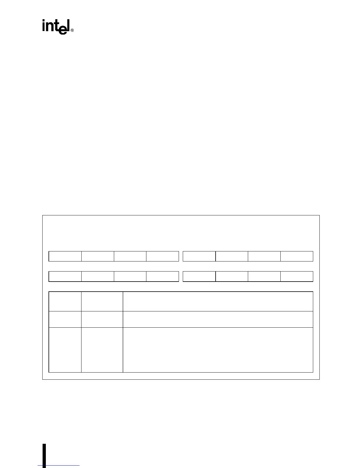
15.4.1 Refresh Clock Interval Register (RFSCIR)
Use RFSCIR to program the interval timer unit’s 10-bit down counter. The refresh counter value
is a function of DRAM specifications and processor frequency as follows:
,
where X = 128 or the # of DRAM rows, whichever is greater.
The DRAM refresh period is the time required to refresh all rows in the DRAM device.
NOTE
Because the lower seven address bits come from a linear-feedback shift
register, which generates all address bit combinations in a nonsequential order,
X in the equation above must never be less than 128 to ensure proper refresh of
all the rows in a DRAM device that has less than 128 rows.
Figure 15-2. Refresh Clock Interval Register (RFSCIR)
Refresh Clock Interval
RFSCIR
(read/write)
Expanded Addr:
ISA Addr:
Reset State:
F4A2H
—
0000H
15 8
———— ——RC9RC8
7 0
RC7 RC6 RC5 RC4 RC3 RC2 RC1 RC0
Bit
Number
Bit
Mnemonic
Function
15–10 — Reserved. These bits are undefined; for compatibility with future devices,
do not modify these bits.
9–0 RC9:0 Refresh Counter Value:
Write the counter value to these ten bits. The interval counter counts
down from this value. When the interval counter reaches one, the control
unit initiates a refresh request (provided it does not have a request
pending). The counter value is a function of DRAM specifications and
processor frequency (see the equation above).
counter value
DRAM refresh period (µs) processor clock (MHz)×
X
-----------------------------------------------------------------------------------------------------------------------------------------
=