18-9
JTAG TEST-LOGIC UNIT
The boundary-scan register (BOUND) holds data to be applied to the pins or data observed at the
pins. Each bit corresponds to a specific pin (Table 18-5).
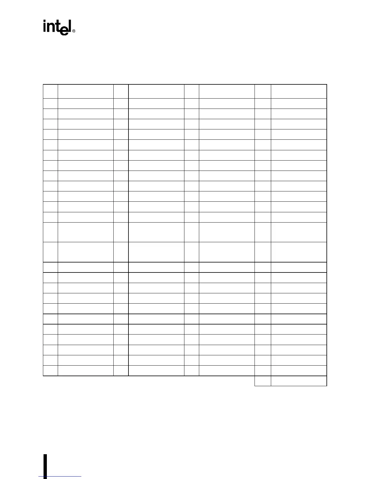
Table 18-5. Boundary-scan Register Bit Assignments
Bit Pin Bit Pin Bit Pin Bit Pin
0 M/IO# 25 A15 50 TMROUT2 75 P2.2
1 D/C# 26 A16/CAS0 51 TMRGATE2 76 P2.3
2 W/R# 27 A17/CAS1 52 INT4/TMRCLK0 77 P2.4
3 READY# 28 A18/CAS2 53 INT5/TMRGATE0 78 DACK0#
4 BS8# 29 A19 54 INT6/TMRCLK1 79 P2.5/RXD0
5 RD# 30 A20 55 INT7/TMRGATE1 80 P2.6/TXD0
6 WR# 31 A21 56 STXCLK 81 P2.7
7 BLE# 32 A22 57 FLT# 82 UCS#
8 BHE# 33 A23 58 P1.0 83 CS6#/REFRESH#
9 ADS# 34 A24 59 P1.1 84 LBA#
10 NA# 35 A25 60 P1.2 85 D0
11 A1 36 SMI# 61 P1.3 86 D1
12
A2
37 P3.0/TMROUT0/
INT9
62
P1.4
87
D2
13
A3
38 P3.1/TMROUT1/
INT8
63
P1.5
88
D3
14 A4 39 SRXCLK 64 P1.6/HOLD 89 D4
15 A5 40 SSIORX 65 RESET 90 D5
16 A6 41 SSIOTX 66 P1.7/HLDA 91 D6
17 A7 42 P3.2/INT0 67 DACK1#/TXD1 92 D7
18 A8 43 P3.3/INT1 68 EOP# 93 D8
19 A9 44 P3.4/INT2 69 WDTOUT 94 D9
20 A10 45 P3.5/INT3 70 DRQ0 95 D10
21 A11 46 P3.6/PWRDOWN 71 DRQ1/RXD1 96 D11
22 A12 47 P3.7/SERCLK 72 SMIACT# 97 D12
23 A13 48 PEREQ/TMRCLK2 73 P2.0 98 D13
24 A14 49 NMI 74 P2.1 99 D14
100 D15
NOTES:
1. Bit 0 is closest to TDI; bit 100 is closest to TDO.
2. The boundary-scan chain consists of 101 bits; however, each bit has both a control cell and a data cell,
so an EXTEST instruction requires 202 shifts (101 bits
× 2 cells).
 Loading...


