A-5
SIGNAL DESCRIPTIONS
P2.7
P2.6
P2.5
P2.4
P2.3
P2.2
P2.1
P2.0
I/O Port 2:
General-purpose, bidirectional I/O port.
CTS0#
TXD0
RXD0
CS4#
CS3#
CS2#
CS1#
CS0#
P3.7
P3.6
P3.5
P3.4
P3.3
P3.2
P3.1
P3.0
I/O Port 3:
General-purpose, bidirectional I/O port.
COMCLK
PWRDOWN
INT3
INT2
INT1
INT0
TMROUT1/INT8
TMROUT0/INT9
PWRDOWN O Powerdown Output:
Indicates that the device is in powerdown mode.
P3.6
RD# O Read Enable:
Indicates that the current bus cycle is a read cycle and the
data bus is able to accept data.
READY# I/O Ready:
Terminates the current bus cycle. The processor drives
READY# when LBA# is active; otherwise, the processor
samples READY# on the falling edge of phase 2 of T2, T2P
or T2i.
—
REFRESH# O Refresh:
Indicates that a refresh bus cycle is in progress and that the
refresh address is on the bus for the DRAM controller.
CS6#
RESET ST System Reset Input:
Suspends any operation in progress and places the
processor into a known reset state.
—
RI1#
RI0#
I Ring Indicator:
Indicates that the modem or data set has received a
telephone ringing signal.
SSIORX
P1.4
RTS1#
RTS0#
O Request to Send:
Indicates that the SIO channel is ready to exchange data
with the modem or data set.
SSIOTX
P1.1
RXD1
RXD0
I Receive Data:
Accepts data from the modem or data set to the SIO
channel.
DRQ1
P2.5
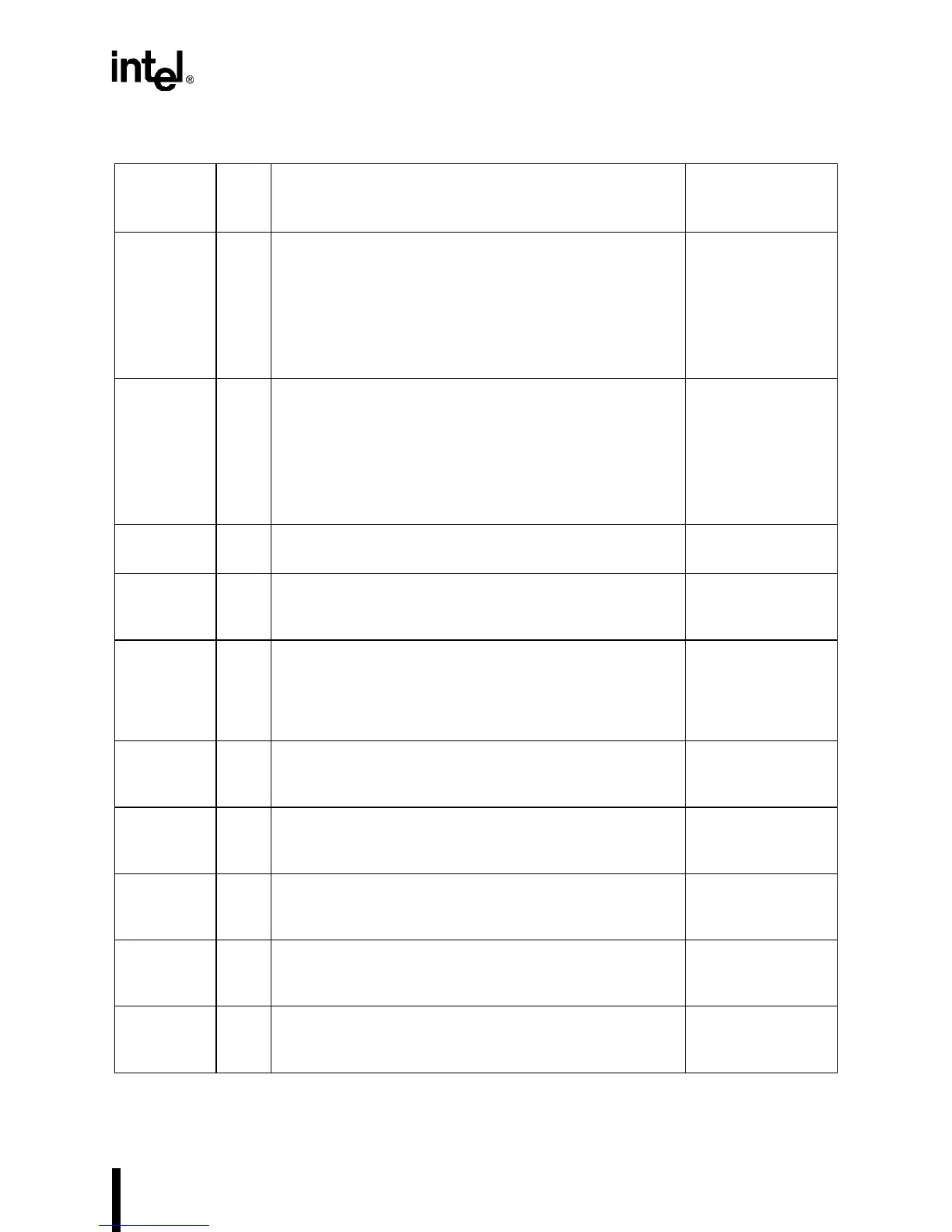
Table A-2. Description of Signals Available at the Device Pins (Sheet 4 of 6)
Signal Type Name and Description
Multiplexed With
(Alternate
Function)