A-7
SIGNAL DESCRIPTIONS
TMS I Test Mode Select:
Controls the sequence of the test-logic unit’s TAP controller
states. Sampled on the rising edge of TCK.
—
TRST# ST Test Reset:
Resets the test-logic unit’s TAP controller. Asynchronously
clears the data registers and initializes the instruction
register to 0010 (the IDCODE instruction opcode).
—
TXD1
TXD0
O Transmit Data:
Transmits serial data from the corresponding SIO channel.
DACK1#
P2.6
UCS# O Upper Chip-select:
Activated when the address of a memory or I/O bus cycle is
within the address region programmed by the user.
—
V
CC
P System Power:
Provides the nominal DC supply input. Connected
externally to a V
CC
board plane.
—
V
SS
G System Ground:
Provides the 0 volt connection from which all inputs and
outputs are measured. Connected externally to a ground
board plane.
—
WDTOUT O Watchdog Timer Output:
Indicates that the watchdog timer has expired.
—
W/R# O Write/Read:
Indicates whether the current bus cycle is a write cycle or a
read cycle.
—
WR# O Write Enable:
Indicates that the current bus cycle is a write cycle.
—
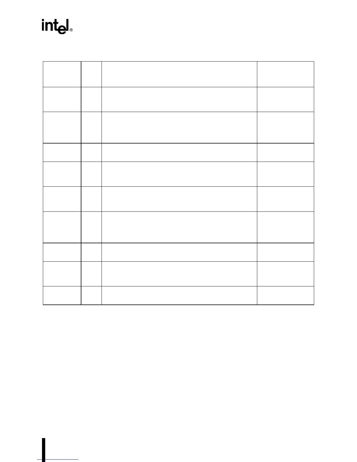
Table A-2. Description of Signals Available at the Device Pins (Sheet 6 of 6)
Signal Type Name and Description
Multiplexed With
(Alternate
Function)