156
Intel
®
855GME Chipset and Intel
®
6300ESB ICH Embedded Platform Design Guide
Integrated Graphics Display Port
The DAC channel (red, green, blue) outputs are routed as single-ended shielded current output
routes that are terminated prior to connecting to the video PI-filter and VGA connector. Table 43
presents the recommended GMCH DAC components.
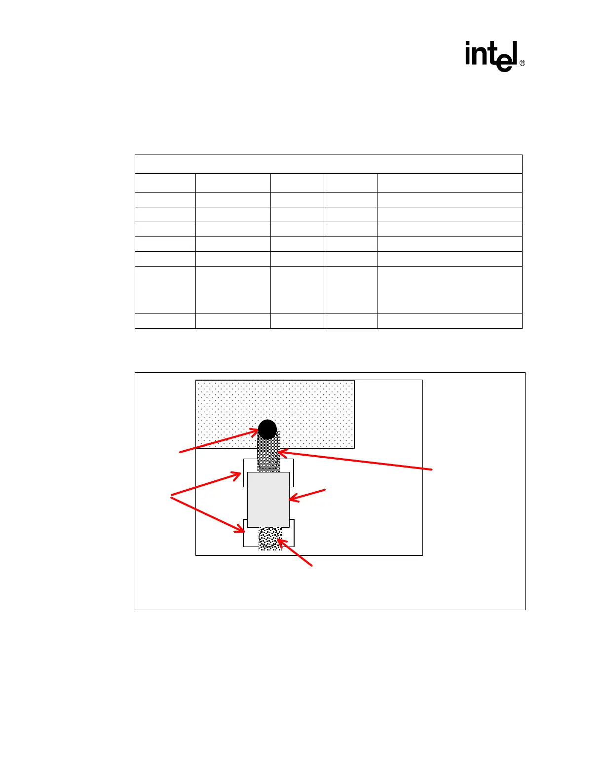
Figure 76 depicts the recommended Rset placement.
Table 43. Recommended GMCH DAC Components
Recommended DAC Board Components
Component Value Tolerance Power Type
R1 75.0 Ω 1 % 1/16 W SMT, Metal Film
Rset 128.0
Ω 1 % 1/16 W SMT, Metal Film
C1 0.1 µF 20 % ----- SMT, Ceramic
C2 0.01 µF 20 % ----- SMT, Ceramic
C 3.3 pF 10 % ----- SMT, Ceramic
D PAC DN006 ------- 350 mW
California Micro Devices – ESD diodes
for VGA
SOIC package
Or equivalent diode array
FB 75
Ω @ 100 MHz -------- ------- MuRata* BLM11B750S
Figure 76. Rset Placement
Large via or multiple
vias straight down to
ground plane
EFSET ball
Rset
Resistor
Resistor
Solder
Pads
Top Side of
Motherboard
Short, wide route
connecting the
resistor to the IREF
ball
should be routed near this
128Ω, 1%, 1/16W
SMT metal film
resistor
Chipset