January 2007 283
Intel
®
855GME Chipset and Intel
®
6300ESB ICH Embedded Platform Design Guide
Schematic Checklist Summary
12.4 Intel
®
6300ESB Checklist
Note: Platforms were validated with all interfaces in use.
Caution: Inputs to the 6300ESB must not be left floating unless otherwise noted.
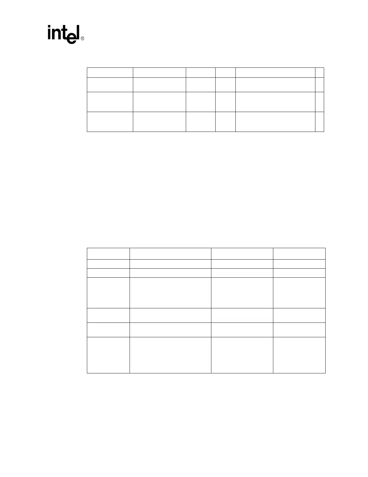
12.4.1 PCI-X Interface Checklist
VCC_GPLL
Connect to
V1P35_GMCH
0.1 µF 1
VCC_ADPLLA
Connect to
V1P35_GMCH with
filter network
0.1 µF
220 µF
1
1
0.1 µH (1 ohm series on CRB) from
power supply to GMCH pins, with
caps on GMCH side of inductor.
VCC_ADPLLB
Connect to
V1P35_GMCH with
filter network
0.1 µF
220 µF
1
1
0.1 µH (1 ohm series on CRB) from
power supply to GMCH pins, with
caps on GMCH side of inductor.
Table 132. PCI-X Interface Checklist
Checklist Items Recommendations Interface not used Reason/Impact
PXAD[32:63] 8.2 KΩ pull-up resistors to VCC3.3 May leave as no connect
PXAD[0:31] No extra pull-ups needed May leave as no connect
PXPCICLK
Ensure this pin is connected to a
66MHz clock output of the clock
generator (CK409) through a 33
Ω
resistor
Ensure this pin is
connected to a 66MHz
clock output of the clock
generator (CK409)
through a 33
Ω resistor
PXRCOMP
30 Ω ±1% pull-down resistor to Vss
30 Ω ±1% pull-down
resistor to Vss
Place close to the
6300ESB
PXACK64# 8.2 K
Ω pull-up resistor to VCC3.3
8.2 K
Ω pull-up resistor to
VCC3.3
PXM66EN 10 K
Ω pull-up resistor to VCC3.3
10 K
Ω pull-up resistor to
VCC3.3
See
PCI-X
Specification 1.0a
for
more
recommendations on
PXM66EN
connections
Table 131. GMCH Decoupling Recommendations Checklist (Sheet 2 of 2)
Pin Name Configuration F Qty Notes
√
NOTE: Decoupling guidelines are recommendations based on our reference board design. Customers may
need to take layout and PCB board design into consideration when deciding on overall decoupling
solution.